Guidewire
a technology of guide wires and wires, applied in the field of guide wires, can solve the problems of time and effort, complicated operations, and complicated operations of endoscopes, and achieve the effect of good operability and efficient operation of procedures
- Summary
- Abstract
- Description
- Claims
- Application Information
AI Technical Summary
Benefits of technology
Problems solved by technology
Method used
Image
Examples
modified example 1
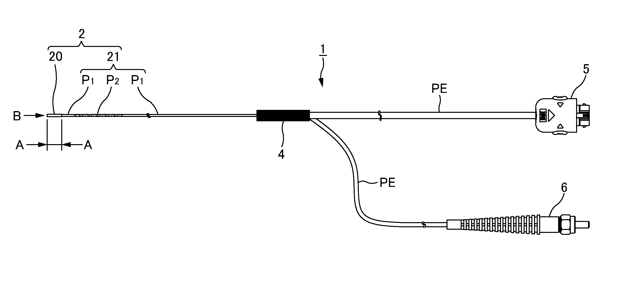
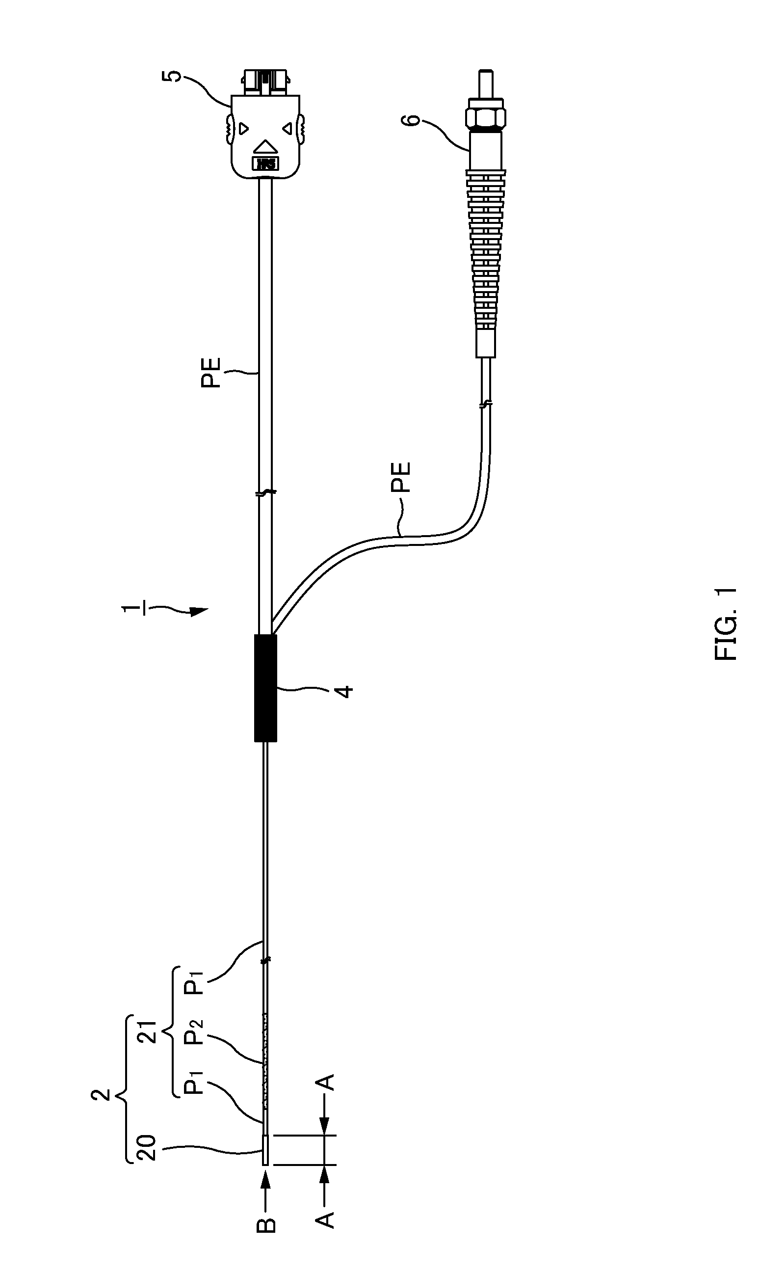
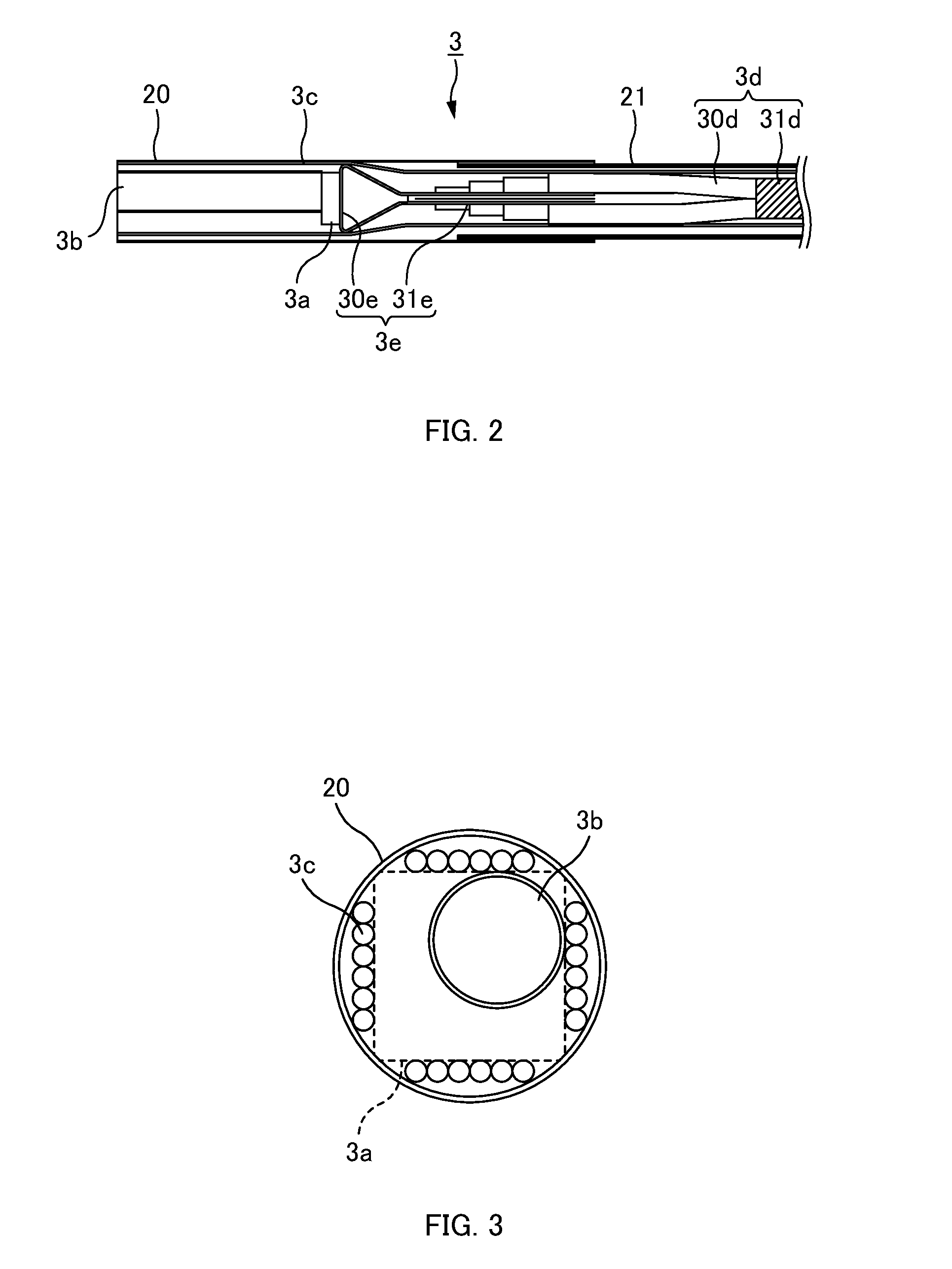
[0095]In the above embodiment mode, the tip portion 20 and the shaft portion 21 are described as separate structures but it is not limited to this. For example, the observation optical system 3 may be arranged to the tip of the long member (inserting portion 2) with the same diameter, and a part (second part P2) with a higher flexibility than other parts (first part P1) may be provided to a part of the long member. In this case, the inserting portion 2 of the guidewire 1 can be made with one member. Accordingly, the tip portion 20 and the shaft portion 21 do not have to be adhered and manufacturing of the guidewire 1 can be simplified.
modified example 2
[0096]Further, the observation optical system is not limited to the example of the above embodiment mode. FIG. 5 is a schematic diagram showing a cross-section of the tip portion 20 of the guidewire 1 in this modified example. An observation optical system 7 in this modified example is configured including an image guide fiber 7a, an objective lens 7b, an image pickup device 7c, and light guide fibers 7d as an illuminating optical system.
[0097]The image guide fiber 7a is inserted into inside the tip portion 20 and the shaft portion 21, and the optical image inside the subject is transmitted via the objective lens 7b. As the image guide fiber 7a, there can be used quartz fiber or plastic optical fiber (POF). The objective lens 7b is provided in front of the incidence plane of the image guide fiber 7a. The image pickup device 7c is provided to the rear end of the inserting portion 2, and captures the optical image transmitted from the image guide fiber 7a. The light guide fibers 7d gu...
modified example 3
[0099]Further, the illuminating optical system is not limited to the light guide fibers 3c. As the illuminating optical system, for example, an LED light source LS can also be used. The LED light source LS is provided inside the tip portion 20, and light is irradiated into the subject. FIG. 6 is a drawing showing a tip surface of the tip portion 20 of the guidewire 1. As shown in FIG. 6, in this modified example, the outgoing surface of the LED light source LS is arranged near the objective lens 3b (the LED light source LS is provided inside the tip portion 20). The LED light source LS irradiates light due to drive power being supplied via the signal lines 30d. In this case, the light guide fibers 3c become unnecessary, thus the inserting portion 2 (shaft portion 21) can be made thinner in diameter. Further, the plug 6 for connecting the light source (not shown) and the guidewire 1 also becomes unnecessary, thus the structure of the guidewire 1 can be simplified.
PUM
 Abstract
Description
Claims
Application Information
 - R&D
- Intellectual Property
- Life Sciences
- Materials
- Tech Scout
- Unparalleled Data Quality
- Higher Quality Content
- 60% Fewer Hallucinations
Browse by: Latest US Patents, China's latest patents, Technical Efficacy Thesaurus, Application Domain, Technology Topic, Popular Technical Reports.
© 2025 PatSnap. All rights reserved.Legal|Privacy policy|Modern Slavery Act Transparency Statement|Sitemap|About US| Contact US: help@patsnap.com


