Hybrid thermal process to separate and transform contaminated or uncontaminated hydrocarbon materials into useful products, uses of the process, manufacturing of the corresponding system and plant

a technology of hydrocarbon materials and thermal processes, which is applied in the production of liquid hydrocarbon mixtures, hydrocarbon distillation, carbonaceous materials, etc., can solve the problems of large large amount of laboratory analysis, and environmental threat, and achieves the effect of improving the amount of light oil recovered and low conten

Active Publication Date: 2016-02-25
ENVIROLLEA
View PDF10 Cites 36 Cited by
  • Summary
  • Abstract
  • Description
  • Claims
  • Application Information

AI Technical Summary

Benefits of technology

[0038]Process for reclaiming useful products from a waste oil, comprising a thermal separation step performed in a vessel at conditions, of temperature and pressure, allowing to substantially avoid cracking of the waste oil and to assure the separation of said heated waste oil into a first heavy oil fraction and into a second light oil fraction having, in comparison with the waste oil, a low content in solids and/or in other contaminants that are different from water and from inert gas. The process is further characterized in that while, during the thermal separation treatment, the waste oil is heated to a temperature about the boiling temperature of the heavy oil fraction, and below the cracking temperature of the waste oil, and at a pressure that is preferably below the atmospheric pressure, the heavy oil fra...

Problems solved by technology

Waste oils, especially used lubricating oils (ULO), are considered a threat to the environment, and is classified as a hazardous product in most jurisdictions.
Among the processes that regenerate ULO into lubricating oil base-stocks, some, such as the acid clay processes, were abandoned or legislated out because of the disposal costs, both financial and environmental, of the by-products such as spent acid and clays.
Because of their high capital and operating costs, these plants must be close to large population centre and/or serve a large collection area, and usually require government subsidies to be viable.
Again, these applications require extensive laboratory analyses.
The process comprises raising a temperature of a feed mixture of fresh waste oil and a recycled non-volatile residue to a range of 400 degrees Celsius to 490 degrees Celsius for a time sufficient to cause pyrolysis of said heavy hydrocarbons contained in the feed mixture, but insufficient to permit substantial undesired polymerization, oxidation and dehydrogenation reactions to take place in said feed mixture; cooling the resulting pyrolized waste oil mixture to a temperature in the range of 300 degrees Celsius to 425 degrees Celsius, and maintaining said tempera...

Method used


Image

  • Hybrid thermal process to separate and transform contaminated or uncontaminated hydrocarbon materials into useful products, uses of the process, manufacturing of the corresponding system and plant
  • Hybrid thermal process to separate and transform contaminated or uncontaminated hydrocarbon materials into useful products, uses of the process, manufacturing of the corresponding system and plant
  • Hybrid thermal process to separate and transform contaminated or uncontaminated hydrocarbon materials into useful products, uses of the process, manufacturing of the corresponding system and plant

Examples


example 1

Marpol

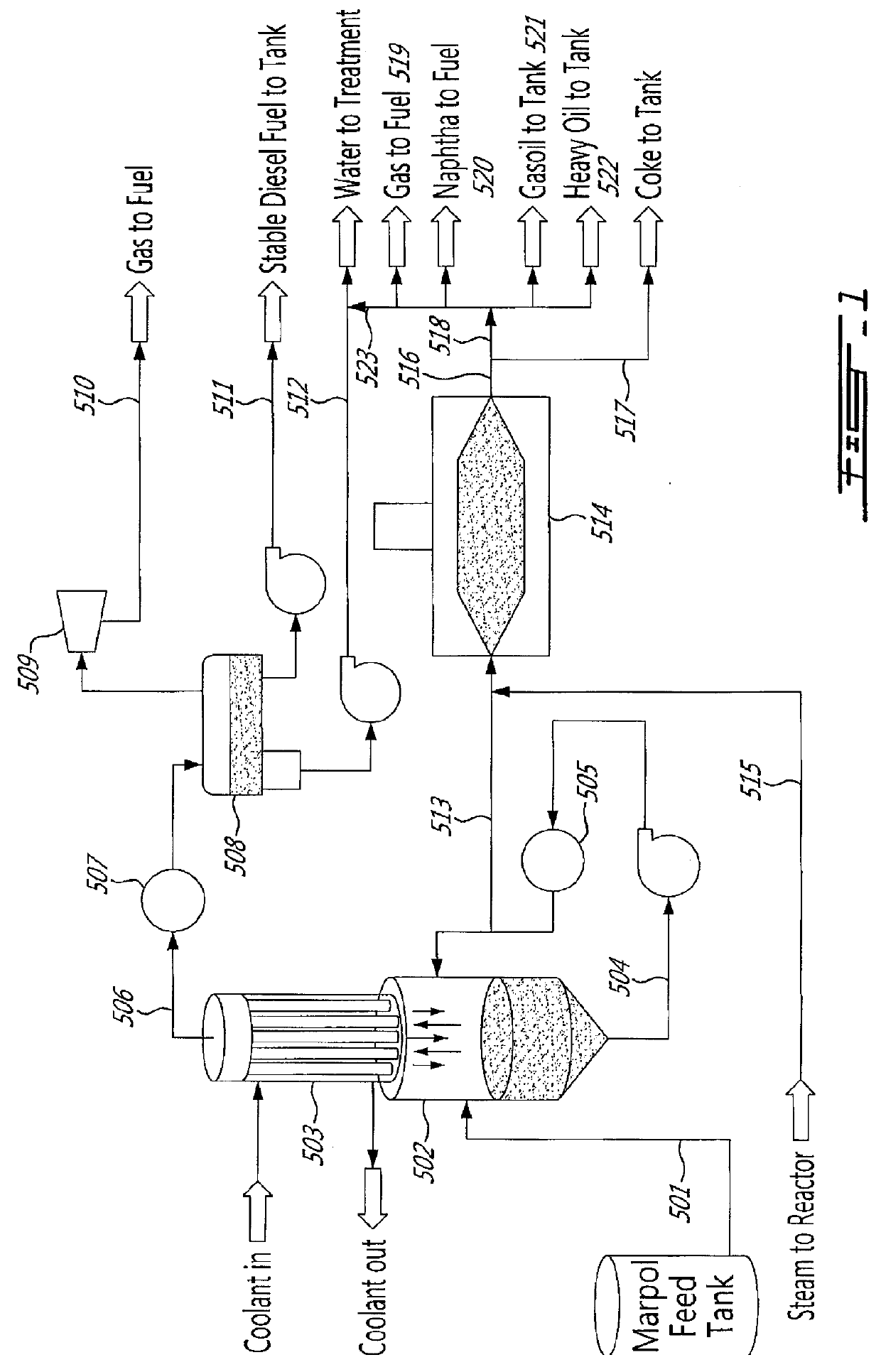
[0272]FIG. 1 illustrates the process when marpol is treated. Marpol, or waste oil from ship fuel tank bottoms, is introduced at 90 degrees Celsius with about 3% weight water (501) into the flash drum (502). It operates under vacuum and is kept at temperatures below the oil's initial thermal cracking temperature. The flash drum can be heated by circulating (504) the bottom oil through a heat exchanger (505), as illustrated here. It can also be heated through a heater or direct heating of the flash drum walls. The oil and water vapours escape the flash drum into the tubes of a self-refluxing condenser, or dephlegmator, (503). Some of the vapours condense in the tubes of the dephlegmator and fall back into the flash drum. The vapours exiting the top of the dephlegmator (506) are cooled in a heat exchanger (507), and the water, oil and gas phases are separated in a phase separator vessel (508). The vacuum is established with a vacuum pump, a compressor or ejectors (509). The gases...

example 2

Used Lubricating Oil

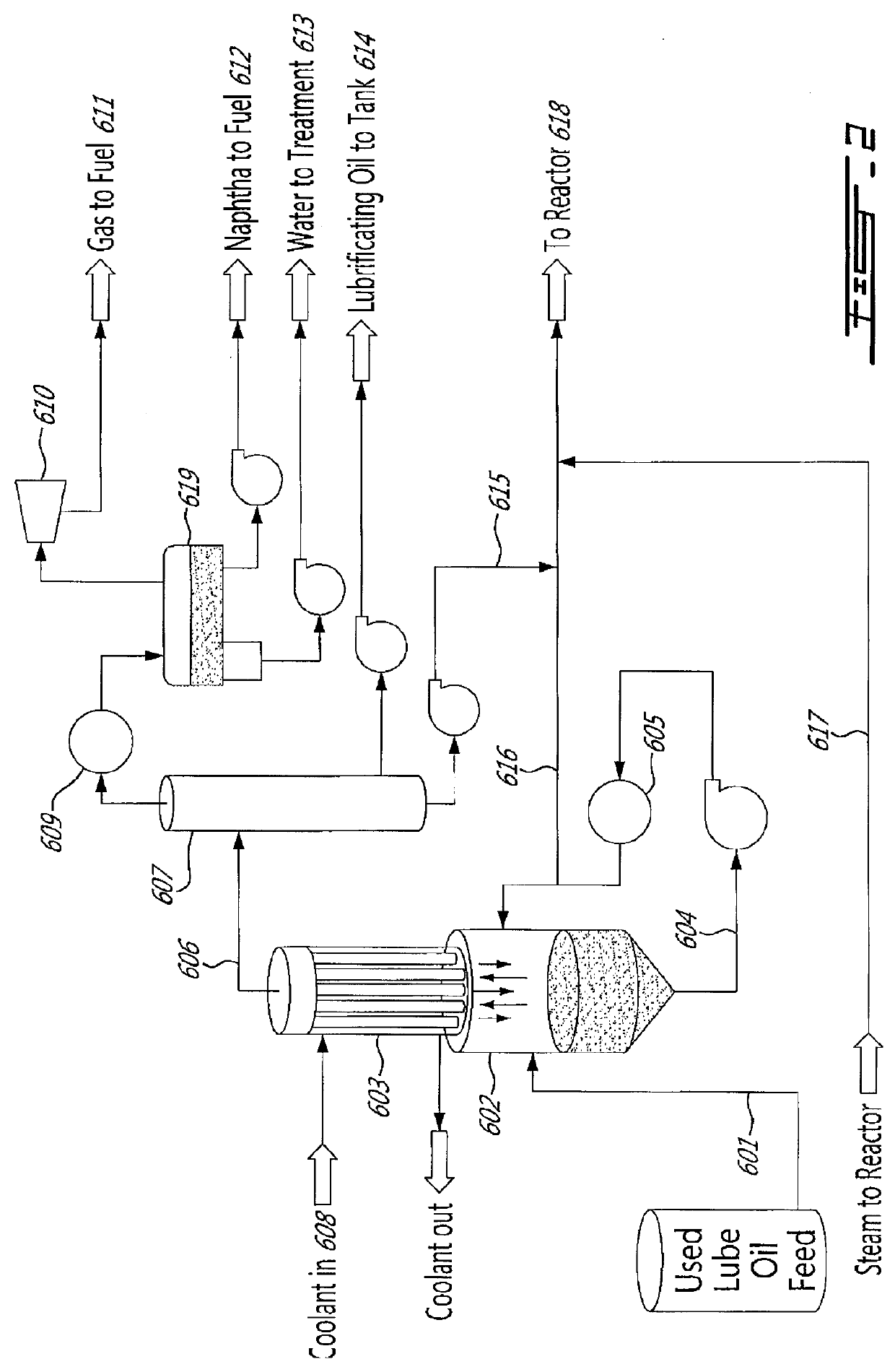
[0293]FIG. 2 illustrates the process when used lubricating oil is treated. Used lubricating oil (601), containing about 5% wt. water, is heated to 90 degrees Celsius and introduced into the flash drum (602). It operates under vacuum and is kept at temperatures below the oil's initial thermal cracking temperature. The flash drum can be heated by circulating (604) the bottom oil through a heat exchanger (605), as illustrated here. It can also be heated through a heater, direct heating of the flash drum walls or by the injection of a hot fluid into the flash drum. The oil and water vapours escape the flash drum into the tubes of a self-refluxing condenser, or dephlegmator, (603). The dephlegmator is cooled with a coolant (608) such as air, water, a cooler oil, or feed oil. Some of the vapours condense in the tubes of the dephlegmator and fall back into the flash drum. The vapours exiting the top of the dephlegmator (606) are routed to a product separation system, sh...

examples 3

Mobile Plant for Thermally Treating a Feed Oil, that is a Contaminated Oil

[0295]The mobile plant represented on FIG. 15, has a capacity of 50 barrels per day (BPD) for thermally treating waste oils, and making useful products without environmentally harmful by-products.

[0296]The mobile plant includes a rotating reactor having the following specifications:[0297]Reactor cylinder internal diameter: 5′

[0298]Reactor cylinder length: 20′

[0299]Heat released: 0.5 MMBtu / hr.

[0300]Conic section heights: 2.5′

[0301]Housing external size: 7′ high 6′ wide and 26′ long

[0302]Following are examples of thermal cracking tests performed in rotating kilns:[0303]Examples 4, 5, and 6 were tests performed using dry waste oil drawn from the same drums to eliminate test result differences due to variations in feed oil quality as much as possible.[0304]Example 4 was performed with the injection of 5% weight. water added to the 16 l / hr. reactor feed oil.[0305]Example 5 kept the same oil feed rate and operating ...


PUM


Abstract

Process for reclaiming useful products from a waste oil, comprising a thermal separation step performed in a vessel at conditions, of temperature and pressure, allowing to substantially avoid cracking of the waste oil and to assure the separation of said heated waste oil into a first heavy oil fraction and into a second light oil fraction having, in comparison with the waste oil, a low content in solids and/or in other contaminants that are different from water and from inert gas. The process is further characterized in that while, during the thermal separation treatment, the waste oil is heated to a temperature about the boiling temperature of the heavy oil fraction, and below the cracking temperature of the waste oil, and at a pressure that is preferably below the atmospheric pressure, the heavy oil fraction of the vapours existing the vessel, in contact with a cooler surface, condenses and falls back into the vessel, while the second fraction, in a gaseous state, is eventually submitted to at least one further separation treatment. When water is present in the waste oil, said water is used to improve the amount of recovered light oils; and/or when no water is present in the waste oil, water or at least one inert gas or at least one component that may become an inert gas by heating may be added to the waste oil or to the thermal separation unit. Uses of the process for environmental applications and for treating used oils and to prepare oil products. Systems for reclaiming useful products from waste oils comprising at least one rotating kiln and at least one self-refluxing condenser and/or at least one dephlegmator.

Description

CROSS REFERENCE TO PRIOR APPLICATION(S)[0001]The present case claims the benefit of Canadian patent application No. 2,783,608 filed 23 Jul. 2012, which is hereby incorporated by reference in its entirety.FIELD OF THE INVENTION[0002]The invention relates to hybrid processes allowing the separation, from waste oil, of useful products and the cracking and / or transformation of the remaining part of the separation into valuable products.[0003]The invention relates to a process to thermally treat contaminated or uncontaminated feed materials such as contaminated or uncontaminated feed oils, more particularly such as used lubricating oils, waste oils, oily tank bottoms, heavy oils, marpol or bitumen, preferably by using a rotating kiln operating under pressure and / or with the injection of a gas, and / or preferably with injection of a sweep gas into the reactor or into its feed stream.[0004]Waste material can also be simultaneously treated with the feedstock and / or the feedstock is submitted...

Claims


Application Information

Patent Timeline
IPC IPC(8): C10G7/00B01D3/14C10B55/00C10G1/10C10G3/00C10G9/00C10G55/04
CPCC10G7/006C10G3/40C10G1/10B01D3/143C10G9/00C10B55/00C10G55/04C10G7/003B01J4/002B01J8/002B01J8/0055B01J8/085B01J8/087B01J8/10B01J19/006B01J19/28C10B31/12C10B47/30C10G1/02B01J2219/0077B01J2219/00768B01J2219/00777B01J2219/187B01J2208/00504B01J2208/00761B01J2208/0084B01J2208/00902B01J2208/00867B01J2219/00254B01J2219/00157B01J2219/00247Y02P30/20C10G31/06C10G7/06C10G2300/1007B01D3/346
Inventor WHEELER, LUCIE B.BERTRAND, LOUIS
Owner ENVIROLLEA
Why Eureka
Try Eureka