Heat release rate waveform generating device and combustion state diagnostic system for internal combustion engine

a technology of emission rate waveform and combustion state, which is applied in the direction of machines/engines, electrical control, mechanical equipment, etc., can solve the problems of insufficient reliability, inability to obtain sufficient accuracy based on in-cylinder environment, and inability to determine accurate combustion state, etc., to achieve high reliability and improve diagnosis accuracy

Active Publication Date: 2016-02-25
TOYOTA JIDOSHA KK
View PDF9 Cites 18 Cited by
  • Summary
  • Abstract
  • Description
  • Claims
  • Application Information

AI Technical Summary

Benefits of technology

[0047]With the above-described heat release rate waveform generating device and combustion state diagnostic system according to the invention, the space inside the cylinder is divided into the internal region inside the cavity and the external region outside the cavity and then the ideal heat release rate waveform is obtained for each of the regions, with the result that it is possible to obtain high reliability on the ideal heat release rate waveform. When an abnormality of a combustion state is diagnosed by utilizing the ideal heat release rate waveform, it is possible to improve the accuracy of diagnosis.

Problems solved by technology

However, in an existing method of generating an ideal heat release rate waveform, sufficient accuracy based on an in-cylinder environment, such as an in-cylinder gas temperature, is not obtained, and sufficient reliability is not obtained, for example, when an actual combustion state is diagnosed by utilizing the ideal heat release rate waveform.
That is, the inventors focused on the fact that temperature fields that significantly deviate from the in-cylinder average gas temperature may be present in the cylinder and these temperature differences cause a deviation, or the like, of ignition timing, and become an obstacle to determine an accurate combustion state (generate the ideal heat release rate waveform).
However, in order to highly accurately define the combustion state inside the cylinder, it is insufficient to just take a heat loss into consideration.

Method used


Image

  • Heat release rate waveform generating device and combustion state diagnostic system for internal combustion engine
  • Heat release rate waveform generating device and combustion state diagnostic system for internal combustion engine
  • Heat release rate waveform generating device and combustion state diagnostic system for internal combustion engine

Examples


first embodiment

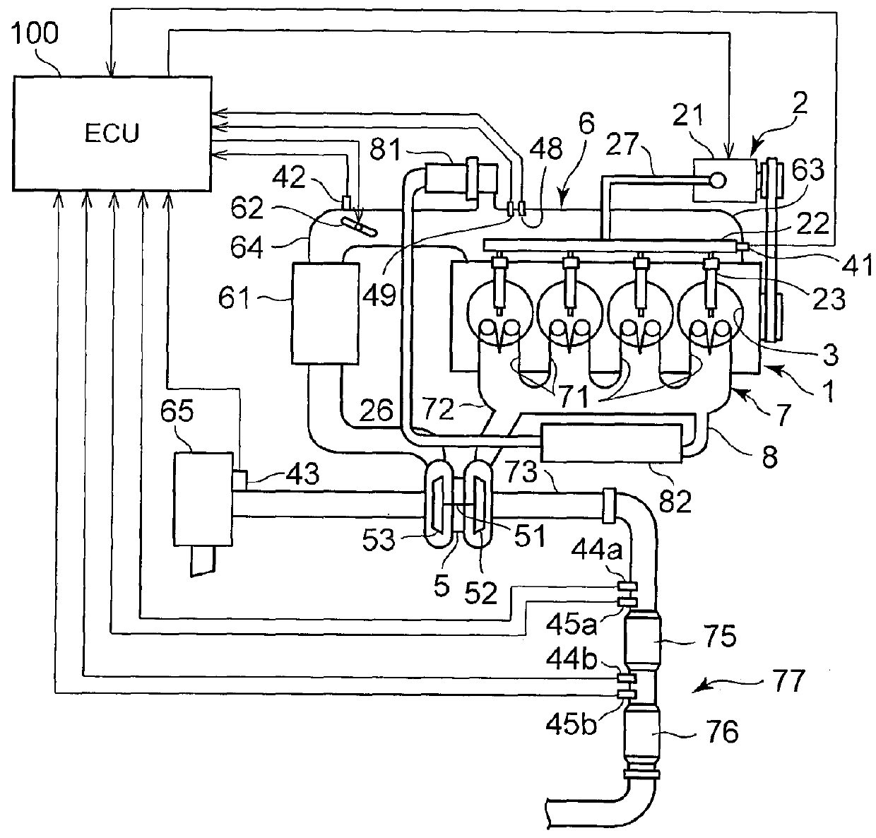
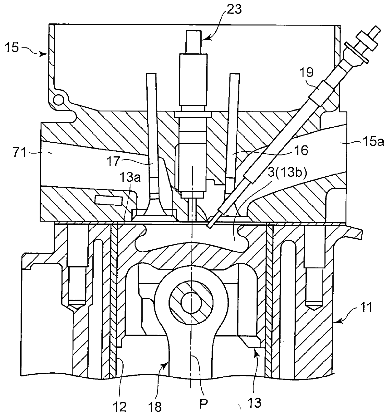
[0082]Initially, a first embodiment will be described. The configuration of the engine will be described. FIG. 1 is a schematic configuration view of the diesel engine 1 (hereinafter, simply referred to as engine) and its control system according to the present embodiment. FIG. 2 is a cross-sectional view that shows each combustion chamber 3 of the diesel engine 1 and its peripheral portion.

[0083]As shown in FIG. 1, the engine 1 according to the present embodiment is configured as a diesel engine system that includes a fuel supply system 2, the combustion chambers 3, an intake system 6, an exhaust system 7, and the like, as major components.

[0084]The fuel supply system 2 is configured to include a supply pump 21, a common rail 22, injectors (fuel injection valves) 23, an engine fuel passage 27, and the like.

[0085]The supply pump 21 draws fuel from a fuel tank, pressurizes the drawn fuel to a high pressure, and then supplies the high-pressure fuel to the common rail 22 via the engine...

second embodiment

[0216]Next, a second embodiment will be described. In the present embodiment, each of the extra-cavity region and the intra-cavity region is further subdivided, an ideal heat release rate waveform model is generated for each of the subdivided regions, ideal heat release rate waveforms are generated by filtering the ideal heat release rate waveform models. Hereinafter, description will be specifically made.

[0217]When the injection amount of fuel injected from the injector 23 is relatively large, main spray (spray mass) reaches to a region far from the injector 23 because of its penetration force.

[0218]For example, when fuel is injected to the extra-cavity region, the fuel reaches to near the wall face of the cylinder bore 12 because of its penetration force. Therefore, the fuel density of spray is relatively low at a portion around the injector 23, and the fuel density of spray is relatively high at an outer peripheral side (the wall face side of the cylinder bore 12).

[0219]Similarly...


PUM


Abstract

In a diesel engine, an inside of a cylinder is divided into intra-cavity and extra-cavity regions. Ideal heat release rate waveform models, each formed of an isosceles triangle in which each oblique line gradient is a reaction rate, an area is a reaction amount and a base length is a reaction period with a reaction start temperature as a base point, are generated respectively for a vaporization reaction, low-temperature oxidation reaction, thermal decomposition reaction and high-temperature oxidation reaction of injected fuel for each region. An ideal heat release rate waveform of the reaction modes is generated by smoothing the ideal heat release rate waveform models through filtering and combining the ideal heat release rate waveforms, and is compared with an actual heat release rate waveform obtained from a detected in-cylinder pressure. A reaction mode having a deviation larger than or equal to a predetermined amount is diagnosed as being abnormal.

Description

BACKGROUND OF THE INVENTION[0001]1. Field of the Invention[0002]The invention relates to a device that generates a heat release rate waveform of a compression self-ignition internal combustion engine, typically, a diesel engine, and a system that diagnoses an actual combustion state by utilizing the generated heat release rate waveform.[0003]2. Description of Related Art[0004]As is conventionally known, in a diesel engine (hereinafter, which may also be simply referred to as engine) that is used as an automobile engine, or the like, a control map is generated by obtaining suitable values of various control parameters, such as a fuel injection amount, based on an engine operating state that is determined on the basis of a rotation speed and load of the engine through an experiment or simulation, and these are stored in an engine control electronic control unit (engine ECU). The engine ECU is configured to control the engine while referencing suitable values on the control map.[0005]W...

Claims


Application Information

Patent Timeline
Patent Type & Authority Applications(United States)
IPC IPC(8): F02D41/14F02B9/04
CPCF02B9/04F02D41/1473F02D41/403F02D35/02F02D35/023F01B3/06F02B23/0648F02B23/0669F02B23/0672F02M26/05Y02T10/12Y02T10/40
Inventor NADA, MITSUHIRO
Owner TOYOTA JIDOSHA KK
Why Eureka
Try Eureka