Inspection Apparatus, Inspection Method And Manufacturing Method

a technology of inspection apparatus and manufacturing method, applied in the direction of photomechanical apparatus, instruments, printers, etc., can solve the problems of limiting the detection ability of weak targets, affecting the detection accuracy of weak targets, etc., so as to achieve the effect of achieving these requirements, it is increasingly difficult to have good anti-reflection coatings over a large wavelength rang

Active Publication Date: 2016-03-03
ASML NETHERLANDS BV
View PDF0 Cites 53 Cited by
  • Summary
  • Abstract
  • Description
  • Claims
  • Application Information

AI Technical Summary

Benefits of technology

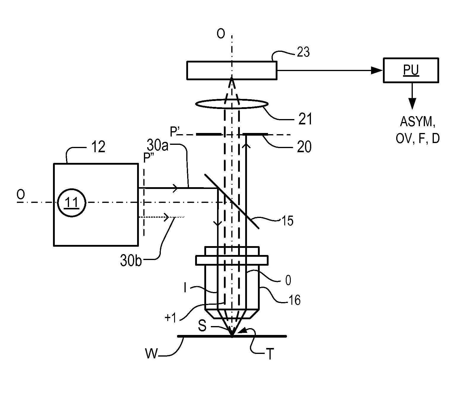
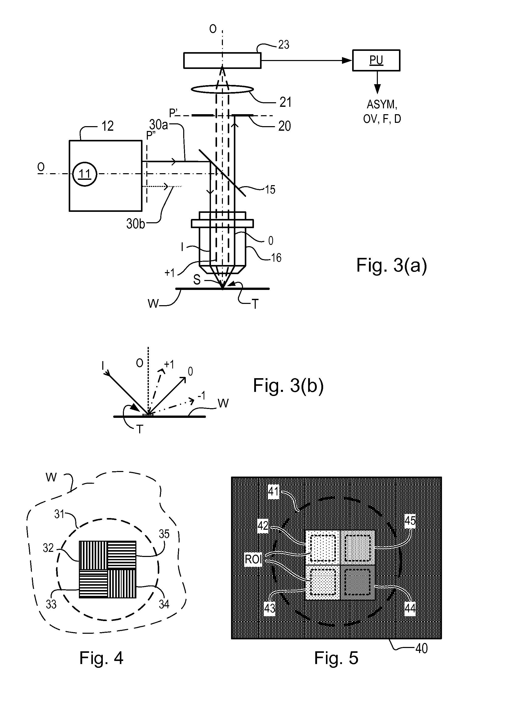
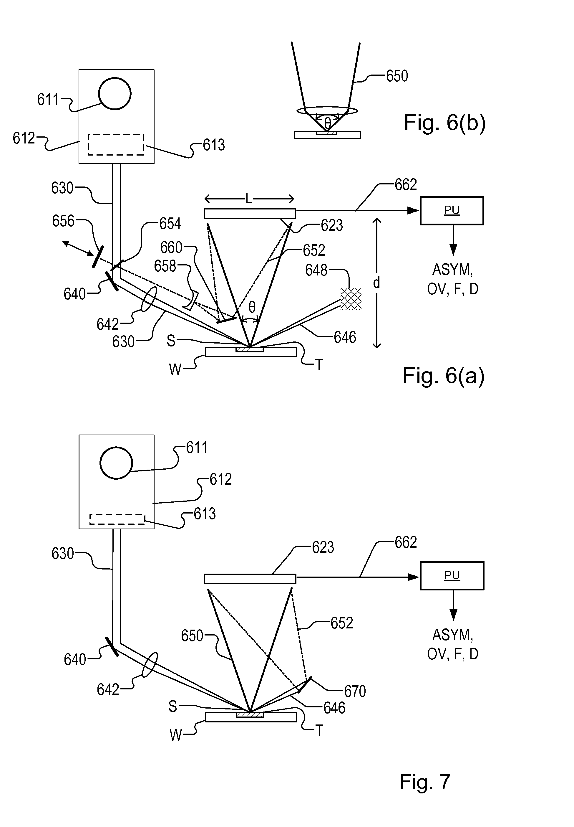
[0013]Such an apparatus can be used to perform so-called “lensless” imaging. This avoids the difficulties associated with the complex broadband, high-NA objective. The image obtained and used to measure properties of the target is called a “synthetic image” because it never existed in the physical world: it exists only as data and is obtained by computation from data representing the complex field. The calculation of the complex field and then the calculation of the synthetic image can be designed to simulate the ...

Problems solved by technology

Realizing these requirements typically involves significant compromises.
Each of these elements contributes to internal scattering which limits the detectability of weak targets.
Also it becomes increasing...

Method used


Image

  • Inspection Apparatus, Inspection Method And Manufacturing Method
  • Inspection Apparatus, Inspection Method And Manufacturing Method
  • Inspection Apparatus, Inspection Method And Manufacturing Method

Examples


Embodiment Construction

[0037]Before describing embodiments of the invention in detail, it is instructive to present an example environment in which embodiments of the present invention may be implemented.

[0038]FIG. 1 schematically depicts a lithographic apparatus LA. The apparatus includes an illumination system (illuminator) IL configured to condition a radiation beam B (e.g., UV radiation or DUV radiation), a patterning device support or support structure (e.g., a mask table) MT constructed to support a patterning device (e.g., a mask) MA and connected to a first positioner PM configured to accurately position the patterning device in accordance with certain parameters; two substrate tables (e.g., a wafer table) WTa and WTb each constructed to hold a substrate (e.g., a resist coated wafer) W and each connected to a second positioner PW configured to accurately position the substrate in accordance with certain parameters; and a projection system (e.g., a refractive projection lens system) PS configured t...


PUM


Abstract

Metrology targets are formed on a substrate (W) by a lithographic process. A target (T) comprising one or more grating structures is illuminated with spatially coherent radiation under different conditions. Radiation (650) diffracted by from said target area interferes with reference radiation (652) interferes with to form an interference pattern at an image detector (623). One or more images of said interference pattern are captured. From the captured image(s) and from knowledge of the reference radiation a complex field of the collected scattered radiation at the detector. A synthetic radiometric image (814) of radiation diffracted by each grating is calculated from the complex field. From the synthetic radiometric images (814, 814′) of opposite portions of a diffractions spectrum of the grating, a measure of asymmetry in the grating is obtained. Using suitable targets, overlay and other performance parameters of the lithographic process can be calculated from the measured asymmetry.

Description

BACKGROUND[0001]1. Field of the Invention[0002]The present invention relates to inspection apparatus and methods usable, for example, to perform metrology in the manufacture of devices by lithographic techniques. The invention further relates to an illumination system for use in such inspection apparatus and to methods of manufacturing devices using lithographic techniques. The invention yet further relates to computer program products for use in implementing such methods.[0003]2. Background Art[0004]A lithographic apparatus is a machine that applies a desired pattern onto a substrate, usually onto a target portion of the substrate. A lithographic apparatus can be used, for example, in the manufacture of integrated circuits (ICs). In that instance, a patterning device, which is alternatively referred to as a mask or a reticle, may be used to generate a circuit pattern to be formed on an individual layer of the IC. This pattern can be transferred onto a target portion (e.g., includin...

Claims


Application Information

Patent Timeline
IPC IPC(8): G01B11/00G01N21/956G03F7/20
CPCG01B11/00G01N21/956G01N2201/12G03H2001/0458G03F7/70625G03F7/70633G03F7/70641G03F7/70141G03H2001/0033G03H2001/0204G03H1/0443
Inventor DEN, BOEF, ARIE, JEFFREYMATHIJSSEN, SIMON, GIJSBERT, JOSEPHUSPANDEY, NITESHWITTE, STEFAN, MICHIELEIKEMA, KJELD
Owner ASML NETHERLANDS BV
Why Eureka
Try Eureka