Capacitor simulation method and capacitor nonlinear equivalent circuit model

a capacitor and simulation method technology, applied in the field of capacitor simulation methods and capacitor nonlinear equivalent circuit models, can solve the problem that the circuit model is not suited for circuit simulation, and achieve the effect of simple configuration and high precesion

Active Publication Date: 2016-03-03
MURATA MFG CO LTD
View PDF15 Cites 6 Cited by
  • Summary
  • Abstract
  • Description
  • Claims
  • Application Information

AI Technical Summary

Benefits of technology

[0049]According to the present disclosure, as described above, the capacitor simulation method and nonlinear equivalent circuit model enabling dynamic simulation of nonlinear characteristics of the capacitor when direct-current voltage is applied with high precesion can be easily provided using a simple configuration.

Problems solved by technology

Such an idealized C circuit model is not suited for circuit simulation because a difference from the impedance characteristics of an actual component, in particular, different in a high-frequency band is too large, but it is useful for an early stage in circuit design or prediction of circuit characteristics.

Method used


Image

  • Capacitor simulation method and capacitor nonlinear equivalent circuit model
  • Capacitor simulation method and capacitor nonlinear equivalent circuit model
  • Capacitor simulation method and capacitor nonlinear equivalent circuit model

Examples


first embodiment

[0088]In the capacitor simulation method and capacitor nonlinear equivalent circuit model in the first embodiment, as described above, the characteristic change ratios kR1(Vdc) and kC1(Vdc) of the passive circuit elements R1 and C1 when the direct-current voltage Vdc is applied are expressed by the approximate function exp(f(x)) using the reference voltage Vref applied to the capacitor as the variable x on the basis of an actually measured value. Accordingly, the characteristic change ratios kR1(Vdc) and kC1(Vdc) expressed by Expressions (10) and (12) are calculated using the approximate function exp(f(x)) in accordance with the referred voltage Vref. The currents IR1(Vdc) and IC1(Vdc) when direct-current voltage is applied can be obtained by causing the difference currents ΔIR1(Vdc) and ΔIC1(Vdc) expressed by Expressions (9) and (11) to flow concurrently with the currents IR1 and IC1 flowing when no direct-current voltage is applied. Consequently, the difference currents ΔIR1(Vdc) ...

second embodiment

[0094]In the passive equivalent circuit model and nonlinear equivalent circuit model in the second embodiment, the series circuit of the resistive element R1 and the capacitive element C1 is connected in series to the parallel circuit of the capacitive element C2 and the resistive element R2, and they constitute a passive circuit element that represents a capacitor equivalent circuit being a target for simulation.

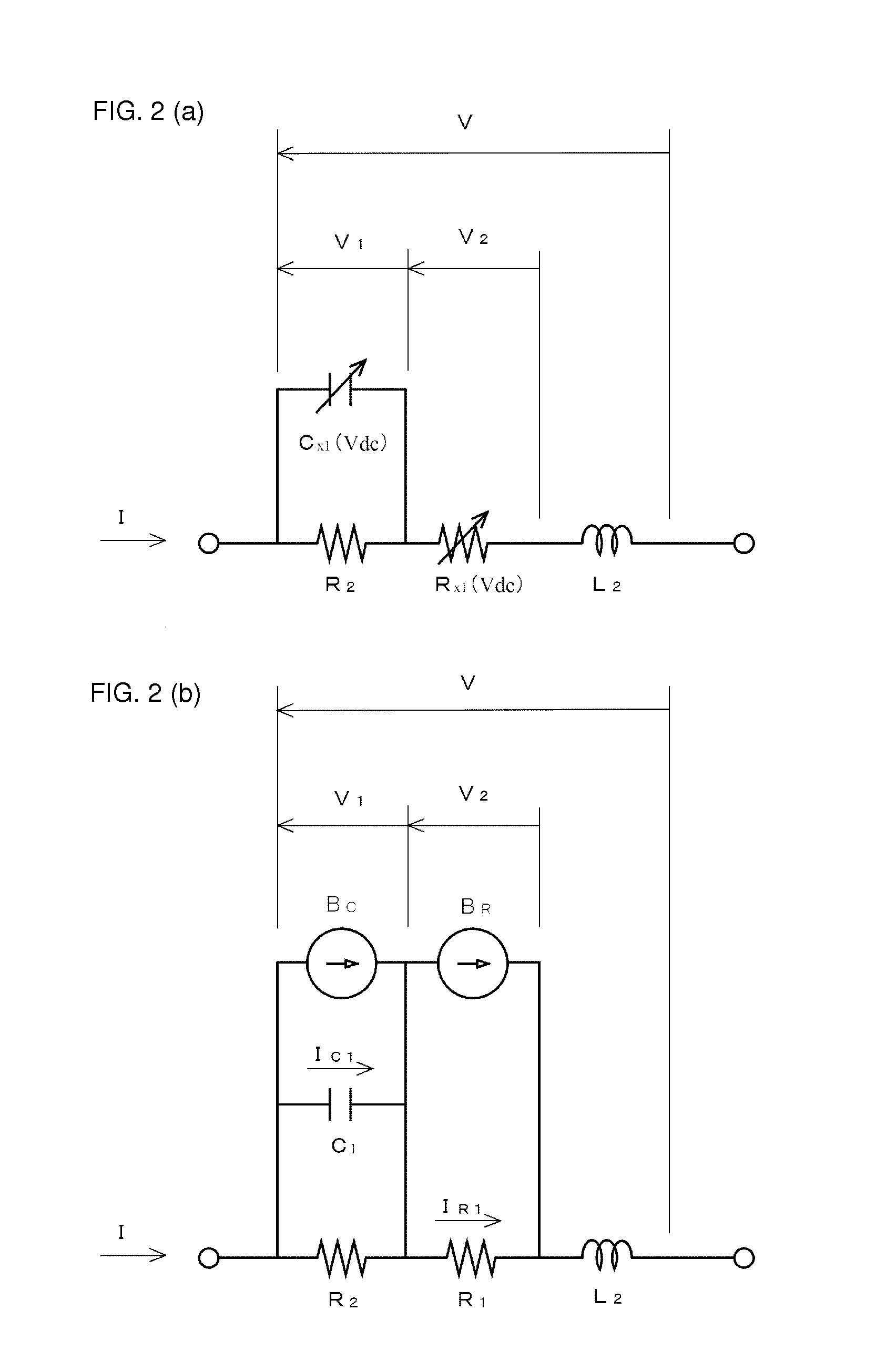
[0095]When the parallel circuit of the capacitive element C2 and the resistive element R2 is transformed into a nonlinear equivalent model, as illustrated in FIG. 5(a), the resistive element R2, whose circuit constant is independent of the direct-current voltage Vdc, is connected in parallel to the control current source BR handled as a behavior current source model, and the capacitive element C2, whose circuit constant is independent of the direct-current voltage Vdc, is connected in parallel to the control current source BC handled as a behavior current source model. Howe...

third embodiment

[0106]FIG. 9 is a circuit diagram that illustrates a nonlinear equivalent circuit model in the present disclosure by representing the nonlinear equivalent circuit model illustrated in FIG. 8(b) as a generalized format. In FIG. 9, the portions identical with or corresponding to those in FIG. 8(b) have the same reference numerals, and the description thereof is omitted.

[0107]In the capacitor simulation method using the general-format nonlinear equivalent circuit model illustrated in FIG. 9, first, the capacitor equivalent circuit is represented using passive circuit elements Rx, Lx, Cx, rx, lx, and cx, and the nonlinear equivalent circuit model illustrated in FIG. 9 is established. Here, the suffix x (x=1, 2, 3, . . . ) on each circuit element indicates the element position 1, 2, 3, . . . of the element numbered from the left to right in sequence in FIG. 9 when the position of the leftmost element in the drawing is defined as 1. Hereinafter, the suffix x is added to each circuit eleme...


PUM


Abstract

A capacitor simulation method and nonlinear equivalent circuit model enabling dynamic simulation of nonlinear characteristics when direct-current voltage is applied with high precesion are easily provided using a simple configuration. An equivalent circuit of a capacitor is represented using a series circuit of passive circuit elements. Characteristic change ratios of the passive circuit elements when a direct-current voltage is applied are expressed as an approximate function on the basis of an actually measured value. A reference voltage is referred to by control current sources connected in parallel to the passive circuit elements. The characteristic change ratios are calculated in accordance with the reference voltage Vref. Difference currents are generated on the basis of the characteristic change ratios and currents flowing when no direct-current voltage is applied, they are caused to flow concurrently with the currents flowing when no direct-current voltage is applied, and thus the nonlinear characteristics are simulated.

Description

CROSS REFERENCE TO RELATED APPLICATIONS[0001]This application claims benefit of priority to International Patent Application No. PCT / JP2014 / 062156 filed May 2, 2014 and JP 2013-102541 filed May 14, 2013, the entire content of each of which is incorporated herein by reference.TECHNICAL FIELD[0002]The present disclosure relates to a capacitor simulation method of simulating nonlinear characteristics of capacitors when direct-current voltage is applied and a capacitor nonlinear equivalent circuit model for use in the simulation.BACKGROUND ART[0003]Simulation methods and equivalent circuit models for electronic components of this kind are used in circuit simulations in electronic circuit design. The circuit simulations employ circuit simulators, such as a simulation program with integrated circuit emphasis (SPICE). Some circuit simulators can be used at websites of producers of electronic components. A user can access a website of a producer of electronic components from a terminal, suc...

Claims


Application Information

Patent Timeline
Patent Type & Authority Applications(United States)
IPC IPC(8): G06F17/50G06F17/10
CPCG06F17/10G06F17/5036G06F30/367
Inventor HIDAKA, SEIJISAKURAGI, ATSUSHI
Owner MURATA MFG CO LTD
Why Eureka
Try Eureka