

Global synchronous pulse width modulation system and method for distributed grid-connected inverter system
- Summary
- Abstract
- Description
- Claims
- Application Information
AI Technical Summary
Benefits of technology
Problems solved by technology
Method used
Image

Examples
embodiment 1
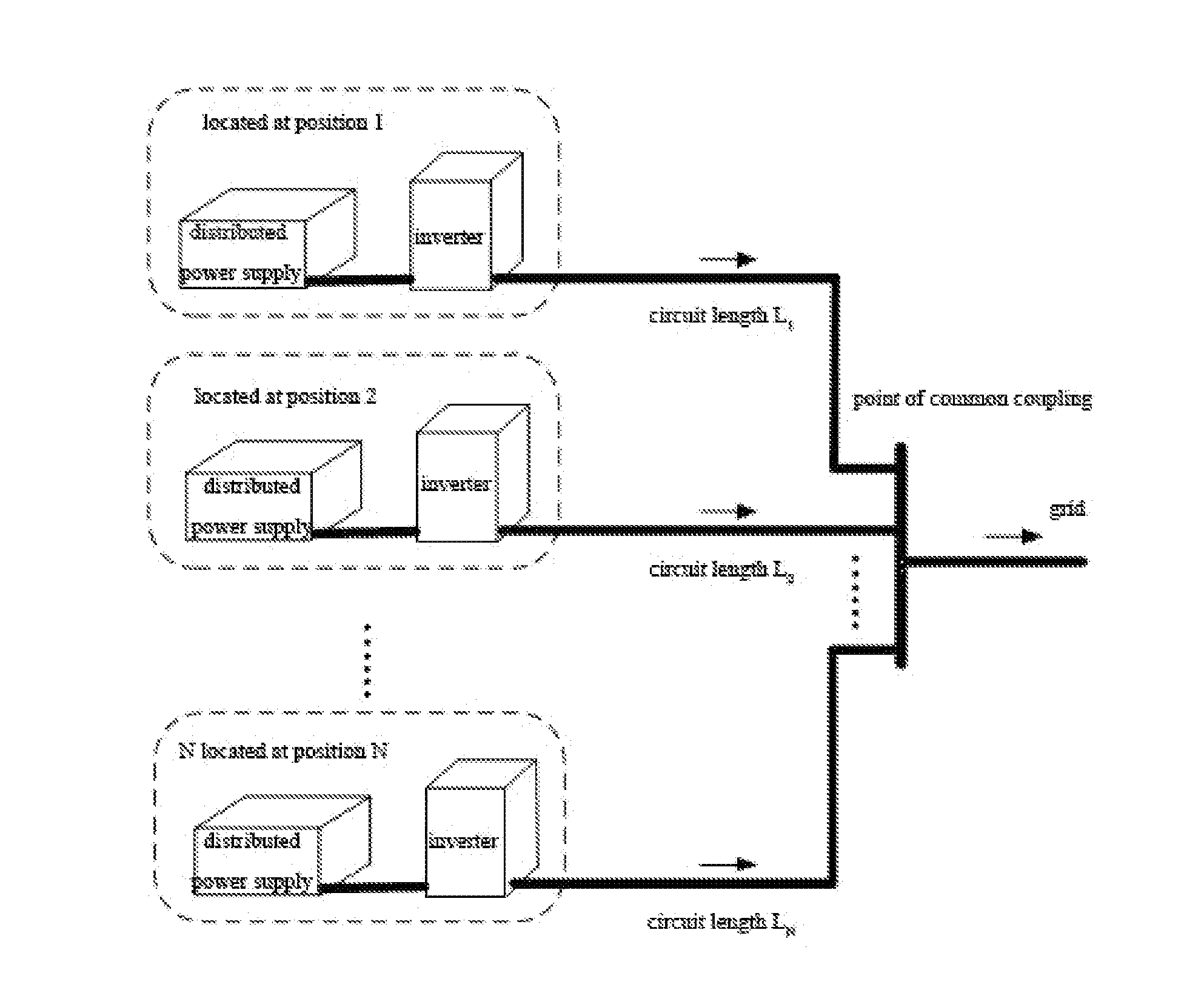
[0060]Corresponding to the condition that the inverters are not grouped, 4 inverters are connected to the point of common coupling in the system, the switching frequency of the inverters is all 20 k, the voltages at the DC sides are all Vdc, and the inductance from the point of common coupling is all L, the inverters are not grouped, N=4, m=1, 2, 3, 4.
[0061]Step 11, the synchronous unit obtains the switching frequency, the voltages at the DC sides and the reactance to the point of common coupling of the inverters.
[0062]The time of one switching period is:
Tc=120×103=50µsΔt(1)=(1-1)Tc / 4=0µsΔt(2)=(2-1)Tc / 4=12.5µsΔt(3)=(3-1)Tc / 4=25µsΔt(4)=(4-1)Tc / 4=37.5µs
[0063]Step 12, setting the synchronous time interval as 1 minute and entering a step 13 after waiting for 1 minute;
step 13, adopting a fast communication mode the synchronous unit: sending a pulse to an optical fiber 1 from a port 1, a rising edge is effective, 12.5 us later sending a pulse to an optical fiber 2 from a port 2, the risin...
embodiment 2
[0065]Corresponding to the condition that the inverters are not grouped, 5 inverters are connected to the point of common coupling in the system, the switching frequency of the inverters is all 20 k, the voltages at the DC sides are all Vdc, and the inductance from the point of common coupling is all L, the inverters are not grouped, N=5, m=1, 2, 3, 4, 5.
[0066]Step 21, the synchronous unit obtains the switching frequency, the voltages at the DC sides and the reactance to the point of common coupling of the inverters.
[0067]The inverters are divided into two groups for control,
the time of one switching period of one group is:
Tc=120×103=50µsΔt(1)=(1-1)Tc / 5=0µsΔt(2)=(2-1)Tc / 5=10µsΔt(3)=(3-1)Tc / 5=20µsΔt(4)=(4-1)Tc / 5=30µsΔt(5)=(4-1)Tc / 5=40µs
[0068]Step 22, the switching frequency is higher, setting the synchronous time interval as 30 seconds and entering a step 23 after waiting for 30 seconds;
step 23, adopting a GPS clock synchronous method:
the synchronous unit: the time of the previous sy...
embodiment 3
[0070]Step 31: corresponding to the condition that the inverters are grouped, 11 inverters are connected to the point of common coupling in the system, the switching frequency of the inverters is all 40 k, but when the voltages at the DC sides and the reactance to the point of common coupling are different, the inverters are marked, the voltage parameters at the DC sides and the reactance parameters of the inverters are as shown in table 1, examples are listed herein for analysis, but do not represent actual parameter values, the inverters are divided into 4 groups according to a method that the Vdcm / Lm sums in the groups are close, the groups are as shown in the table 1, the inverters 1, 2, 3 form the first group, the inverters 4, 5, 6 form the second group, the inverters 7, 8, 9 form the third group, the inverters 10, 11 form the fourth group, N=4, m=1, 2, 3, 4.
TABLE 11234567891011Vdc1.61.20.71.31.50.91.11.30.81.61.7L / e-6H1.51.111.21.31.21.21.20.911.2Vdcm / Lm sum2.86e62.99e62.89e63...
PUM
 Abstract
Description
Claims
Application Information