
Lithographic printing press and method for on-press imaging laser sensitive lithographic plate

Inactive Publication Date: 2016-03-10
TENG GARY GANGHUI
View PDF6 Cites 7 Cited by
  • Summary
  • Abstract
  • Description
  • Claims
  • Application Information

AI Technical Summary

Benefits of technology

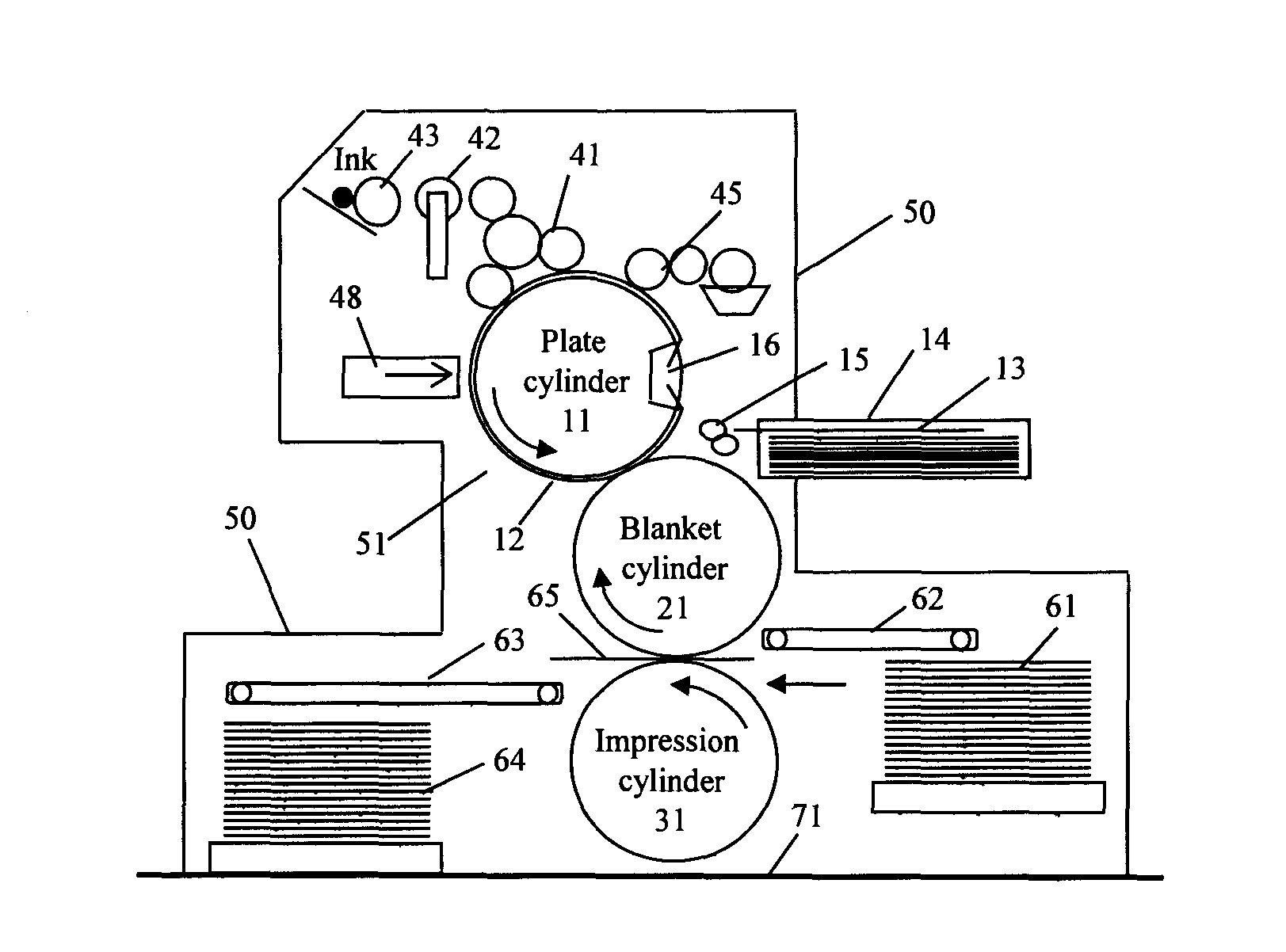
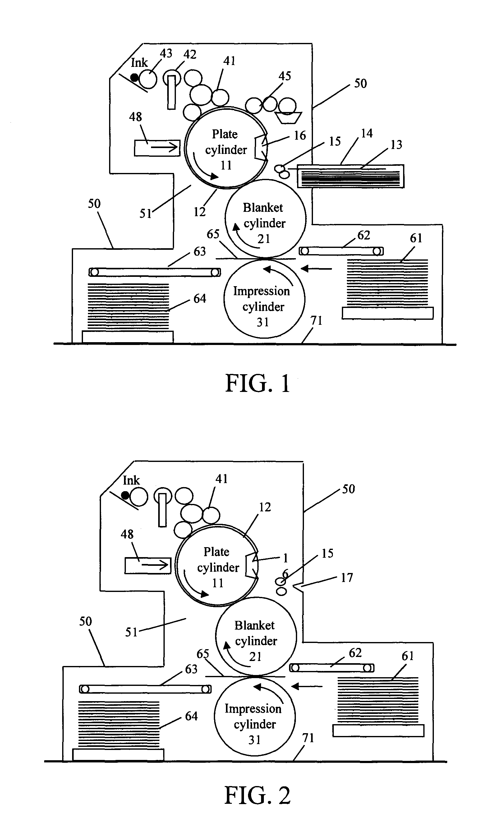
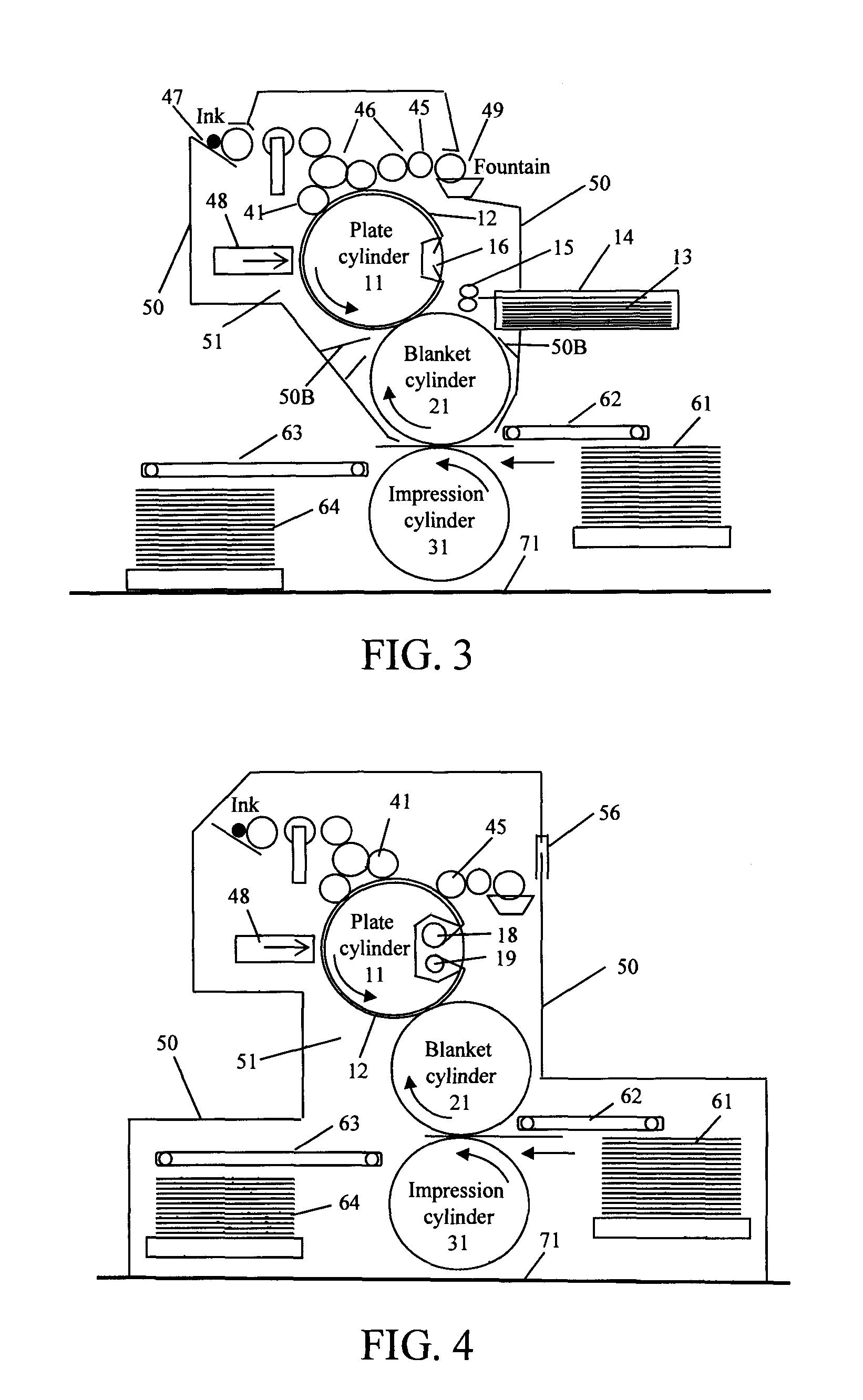
The patent text describes a device that prevents unwanted light from reaching a plate mounted on a plate cylinder, which can cause photo reactions that negatively impact the quality of the printing process. The device includes covers and other press parts that block or reduce the amount of light with wavelengths below 450 nm from reaching the plate. The covers can be non-transparent or only transparent to light with wavelengths above 450 nm. The device can be used in a variety of printing press configurations, including those with a plate cylinder, exposure means, and inking means. The device can be connected to a light-tight cassette or have a light-tight slot for feeding a plate from a cassette or bag. The technical effect of this device is to improve the quality and consistency of printing processes that use photosensitive plates.

Problems solved by technology

Accordingly, photosensitive plates designed for laser imaging generally have limited room light stability.
For example, before being developed to remove the non-hardened areas, frequency-doubled NdYAG laser sensitive plates usually require red room light for handling, violet laser sensitive plates usually require orange or yellow room light for handling, and infrared laser sensitive photopolymer plates usually require yellow room light for handling and have only limited white light stability (due to the use of certain initiator which has spectral sensitivity in the ultraviolet region).
Such limited room light stability is an inherent barrier for the design and use of on-press developable laser sensitive lithographic plate because the pressrooms are generally equipped with white lights, in addition to the difficulties in designing any on-press developable plate with good press performance.
Like conventional presses, these presses with laser imager are not designed to be light-tight so that the plate mounted on the plate cylinder sees the room light.
However, such presses are not suitable for on-press imaging and developing high speed infrared laser sensitive plate that has high sensitivity to the office white light.
Furthermore, such presses, even if installed with a violet or ultraviolet laser, are not suitable for on-press imaging and developing a violet or ultraviolet plate under regular room light because of the very high white light sensitivity of such plate.
Even for infrared laser sensitive plate with low sensitivity to white light comprising infrared absorbing dye, the infrared absorbing dye can often be gradually decomposed under white light, causing background toning and / or reduced photospeed after prolonged exposure to white light.

Method used


Image

  • Lithographic printing press and method for on-press imaging laser sensitive lithographic plate
  • Lithographic printing press and method for on-press imaging laser sensitive lithographic plate
  • Lithographic printing press and method for on-press imaging laser sensitive lithographic plate

Examples


examples 1-5

[0093]This example demonstrates the importance of imaging and on-press developing a high-speed laser sensitive plate in the dark or under safe light.

[0094]An electrochemically roughened, anodized, and polyvinylphosphonic acid treated aluminum sheet was first coated with a 0.1% aqueous solution of polyvinyl alcohol (Celvol 540, from Celanese) with a #6 Meyer rod, followed by drying in an oven at 100° C. for 2 min. The polyvinyl alcohol coated substrate was further coated with the photosensitive layer formulation PS-1 with a #8 Meyer rod, followed by drying in an oven at 90° C. for 2 min.

PS-1ComponentWeight ratiosNeocryl B-728 (Polymer from Zeneca)3.193Sartomer SR-399 (Acrylic monomer from Sartomer)7.630Pluronic L43 (Nonionic surfactant from BASF)0.6492,2-Bis(2-chlorophenyl)-4,4′,5,5′-tetraphenyl-1,1′-1.407biimidazole2-Mercaptobenzoxazole0.8394,4′-Bis(diethylamino)benzophenone0.2812-Butanone86.000

[0095]The photosensitive layer coated plate was further coated with a water-soluble overc...

examples 6-10

[0099]An electrochemically roughened, anodized, and silicate treated aluminum sheet was coated with thermosensitive layer formulation PS-2 using a #8 Meyer rod, followed by drying in an oven at 90° C. for 2 min.

PS-2ComponentWeight ratiosNeocryl B-728 (Polymer from Zeneca)2.73Sartomer SR-399 (Acrylic monomer from Sartomer)6.52Pluronic L43 (Nonionic surfactant from BASF)0.562,4-Bis(trichloromethyl)-6-[(4-ethoxyethylenoxy)-1.00phen-1-yl]-s-triazineADS-830AT (Infrared absorbing cyanine0.10dye from American Dye Source)Acetone90.0

[0100]The thermosensitive layer coated plate was further coated with a water-soluble overcoat OC-2 using a #6 Meyer rod, followed by drying in an oven at 100° C. for 2 min.

OC-2ComponentWeight ratiosAirvol 205 (Polyvinyl alcohol from Air Products)5.00Zonyl FSO (Perfluorinated surfactant from DuPont)0.02Water95.00

[0101]The plate was exposed with an infrared laser plate imager equipped with laser diodes emitting at about 830 nm (Trendsetter from Creo) at a dosage of...


PUM


Abstract

A lithographic printing press having a plate cylinder in a covered compartment suitable for on-press imaging and developing a laser sensitive plate is described. The plate cylinder as well as certain other press parts is covered by non-transparent and / or safe-light-passing-only covers so that no or only limited amount of unsafe light passes onto the plate mounted on the plate cylinder during on-press imaging and development. The plate comprises on a substrate a photosensitive layer soluble or dispersible in ink and / or fountain solution and capable of hardening upon exposure to a laser having a wavelength selected from 200 to 1200 nm. The plate is on-press exposed with the laser, developed with ink and / or fountain solution, and then directly prints inked images to the receiving sheets.

Description

RELATED PATENT APPLICATIONS[0001]This application is a divisional application of U.S. patent application Ser. No. 12 / 176,377 filed Jul. 20, 2008 which is a continuation-in-part application of U.S. patent application Ser. No. 11 / 599,734 filed Nov. 15, 2006 which is a continuation-in-part application of U.S. patent application Ser. No. 11 / 057,663 filed Feb. 14, 2005.FIELD OF THE INVENTION[0002]This invention relates to lithographic printing. More particularly, it relates to lithographic printing press suitable for on-press imaging and developing laser sensitive lithographic printing plate and method of using such press and plate.BACKGROUND OF THE INVENTION[0003]Lithographic printing is generally performed on a lithographic printing press using a lithographic printing plate (also called planographic printing plate). Lithographic printing plate (after process) generally consists of ink-receptive areas (image areas) and ink-repelling areas (non-image areas); the image areas and the non-i...

Claims


Application Information

Patent Timeline
IPC IPC(8): B41F7/02
CPCB41F7/02B41C1/1008B41C1/1075B41C2210/04B41C2210/08B41F7/06B41F13/0024B41M1/06B41P2217/14G03F7/24G03F7/3035
Inventor TENG, GARY, GANGHUI
Owner TENG GARY GANGHUI
Learn More