Alloy Catalyst Material

a catalyst material and alloy technology, applied in the field of alloy catalyst materials, can solve the problems of not being able to use a commercial hydrogen peroxide synthesis process, not being able to meet the requirements of the whole process, not having a commercial process, etc., and achieves the effect of improving selectivity and activity, cheap and easy preparation

Inactive Publication Date: 2016-03-10
DANMARKS TEKNISKE UNIV
View PDF0 Cites 5 Cited by
  • Summary
  • Abstract
  • Description
  • Claims
  • Application Information

AI Technical Summary

Benefits of technology

[0013]In a first aspect the present invention provides an alloy catalyst material, which is very useable for the electrochemical synthesis of hydrogen peroxide from oxygen and hydrogen, or from oxygen and water,

Problems solved by technology

However, there are issues associated with the process.
Moreover, the whole process requires very large amounts of organic solvents and it is not an environmentally friendly process.
Despite significant interest there is no commercial process for the direct hydrogen peroxide synthesis.
Recent advances in the field mainly use a gas mixture of oxygen and hydrogen, but this presents an obvious risk of explosion from the H2/O2 mixture (J. M. Campos-Martin, G. Blanco-Brieva, J. L. G. Fierro, Angew. Chem. Int. Ed., 2006, 45, 6962-6984).
However, regardless of the technology chosen the main difficulty thus

Method used


Image

  • Alloy Catalyst Material
  • Alloy Catalyst Material
  • Alloy Catalyst Material

Examples


example 1

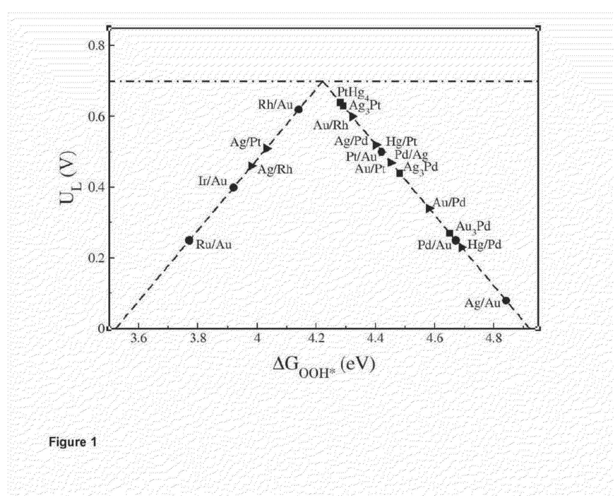
Computational Screening

[0076]Computational Details

[0077]The computational analysis carried out using GPAW, a DFT code based on projected augmented wave (all electron frozen core approximation) method integrated with Atomic Simulation Environment (ASE). The revised Perdew-Burke-Ernzerhof (RPBE) was used as exchange correlation functional. The (111) facet of surface alloys and bulk alloys with face-centered cubic (fcc) crystal structure, i.e. Ag3Pt, Ag3Pd and Au3Pd were modelled using four-layer 2×2 and (√{square root over (3)}×√{square root over (3)})R30° periodically repeated slabs respectively, separated by at least 16Å vacuum between successive slabs. The lattice constants of the surface alloys were assumed to be as the same as that of host metals. An eight-layer 1×1 slab with 17.5Å vacuum between successive slabs was used to model PtHg4 (110) surface. Monkhorest-pack grids with dimensions 6×6×1, 6×6×1 and 4×4×1 were used to sample Brillouin zones of surface 2×2, (√{square root ov...

example 2

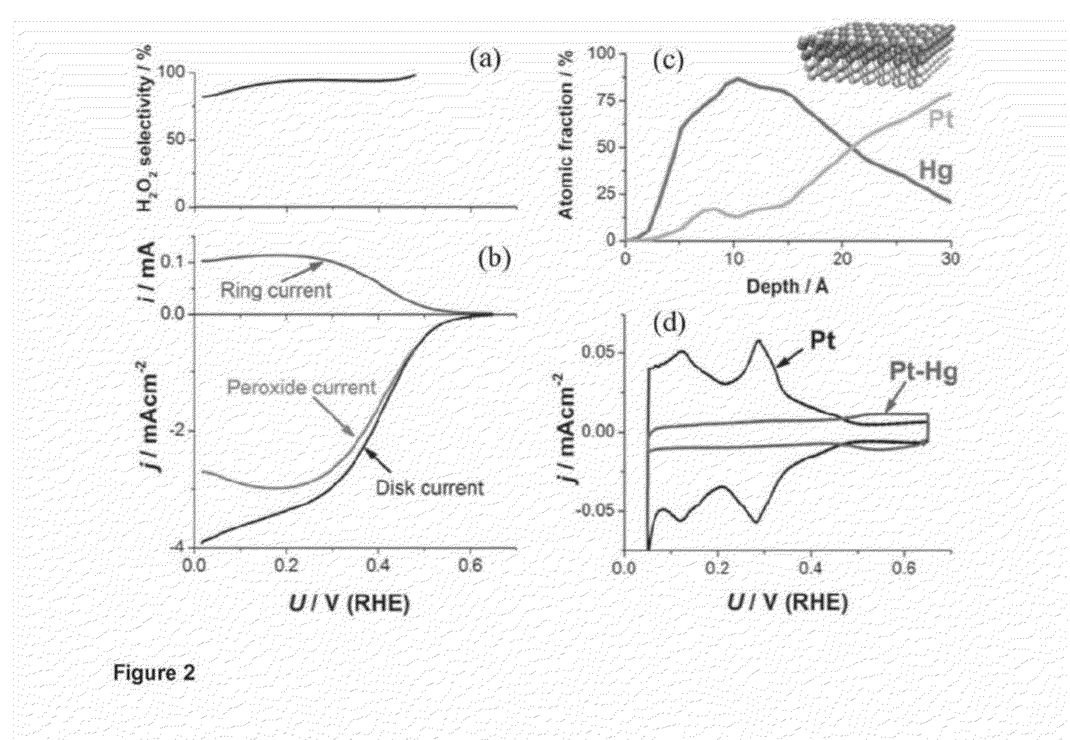
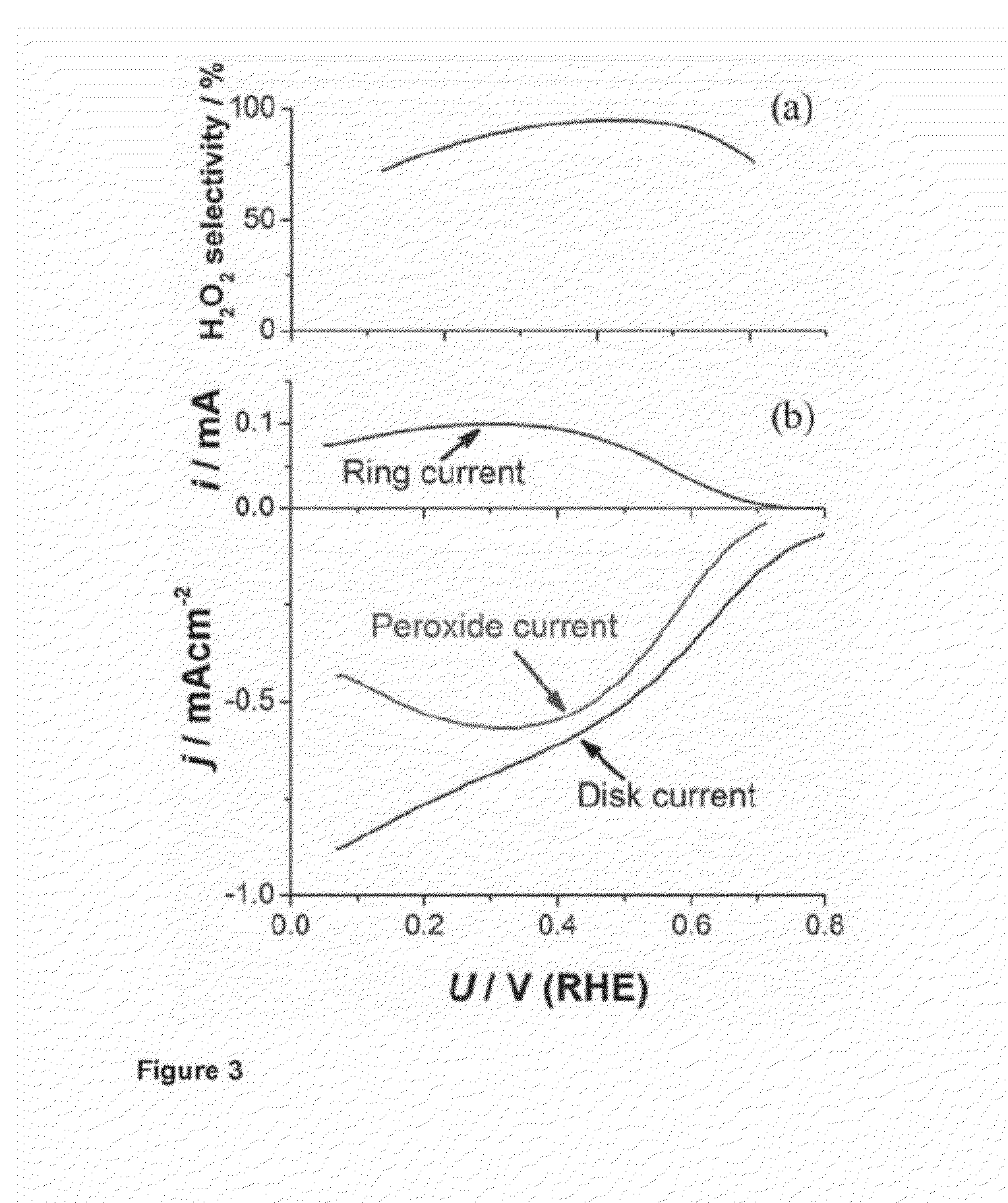
Experimental Testing the PtHg4 Alloy Catalyst Material

[0078]Extended Surface Electrode Preparation

[0079]A platinum polycrystalline electrode was mirror polished to >0.25 μm prior to every experiment and prepared as reported in Verdaguer-Casadevall et al, Journal of Power Sources 2012 Volume 220, Pages 205-210. In short, the electrode was flame annealed at ca. 800 C for 2 min and let cool down under a stream of Argon for 5 min. It was then covered with a droplet of hydrogenated water and embedded into the rotating ring-disk electrode (RRDE) setup. Several voltammograms in nitrogen saturated 0.1 M HClO4 were recorded to ensure a reproducible surface, and then the electrode was moved to an electrodeposition cell containing 0.1 M HClO4+1 mM HgClO4. The potential was swept from open circuit (ca. 1 V) at 50 mVs−1 to 0.2 V, where the potential was stopped for 2 minutes to electrodeposit mercury following the procedure detailed by Wu et al, Electrochimica Acta, 2008 Volume 10 pages 5961-596...


PUM

PropertyMeasurementUnit
Electric potential / voltageaaaaaaaaaa

Abstract

The present invention relates to a novel alloy catalyst material for use in the synthesis of hydrogen peroxide from oxygen and hydrogen, or from oxygen and water. The present invention also relates to a cathode and an electrochemical cell comprising the novel catalyst material, and the process use of the novel catalyst material for synthesising hydrogen peroxide from oxygen and hydrogen, or from oxygen and water.

Description

CROSS-REFERENCE TO RELATED APPLICATION[0001]This application is a national phase entry of pending International Application No. PCT / EP2014 / 058431, filed Apr. 25, 2014 and titled “Alloy Catalyst Material,” which claims priority to and the benefit of European Patent Application No.: 13165265.3, filed Apr. 25, 2013 and titled “Alloy Catalyst Material,” and European Patent Application No.: 13187437.2, filed Oct. 4, 2013 and titled “Alloy Catalyst Material.” The contents of the above-identified Applications are relied upon and incorporated herein by reference in their entirety.FIELD OF INVENTION[0002]The present invention relates to a novel alloy catalyst material for use in the synthesis of hydrogen peroxide from oxygen and hydrogen or from oxygen and water. The present invention also relates to a cathode and an electrochemical cell comprising the novel catalyst material, and the process use of the novel catalyst material for synthesising hydrogen peroxide from oxygen and hydrogen or fr...

Claims


Application Information

Patent Timeline
IPC IPC(8): C25B1/30C22C5/02C22C7/00C25B9/19H01M4/90H01M4/92H01M8/10
CPCC25B1/30C25B11/0405C25B11/0484C25B11/18C25B9/08H01M2300/0082H01M4/921H01M4/9041C22C5/02C22C7/00H01M2008/1095H01M8/1018Y02E60/50C25B11/097C25B11/051C25B11/045C25B11/093C25B9/19C25B11/091
Inventor STEPHENS, IFANVERDAGUER-CASADEVALL, ARNAUWICKMAN, BJORNROSSMEISL, JANMALACRIDA, PAOLOCHORKENDORFF, IBSIAHROSTAMI, SAMIRAESCUDERO-ESCRIBANO, MARIKARAMAD, MOHAMMEDREZA
Owner DANMARKS TEKNISKE UNIV
Why Eureka
Try Eureka