
Eureka
For R&D, Eureka makes reading and utilizing patents & technical documents easy.
Eureka AIR
Designed for self-driven R&D workflows. Generate viable solutions, solve complex R&D challenges, empower your innovation with AI.

Eureka Materials
Designed for material experts only. Revolutionize your material R&D, from search, analyze, to developing new materials.

TechResearch
Generate reliable direction feasibility study reports for your R&D in just a few steps.

TechSeek
Discover and master advanced knowledge NOW. Basics, ideas, possibilities, all at once.

TechMind
As an expert in R&D Theories, TechMind can generates customized viable solutions instantly.

TechRisk
Analyze your overall solution with one click, know your potential R&D risks in advance.

TechMonitor
Get weekly tech updates, stay abreast of the latest tech innovations and key insights.
Electromagnetic resonant coupler and high-frequency transmission device
- Summary
- Abstract
- Description
- Claims
- Application Information
AI Technical Summary
Benefits of technology
Problems solved by technology
Method used
Image

Examples
first embodiment
[0146]Before describing an electromagnetic resonant coupler according to the first embodiment of the present invention, presence of problems as described below in addition to the problems described earlier in the above conventional electromagnetic resonant coupler will be first described with reference to FIG. 46 and others.
[0147]For example, in the case of utilizing an electromagnetic resonant coupler in a circuit using a plurality of insulation elements like insulation elements of an insulated gate driving circuit of an inverter system, there is a possibility of radiating a part of a high frequency used for transmitting a signal or power of the electromagnetic resonant coupler, mutually interfering with adjacent electromagnetic resonant couplers, and causing a malfunction of the system.
[0148]To solve this problem, a transformer having a function similar to that of an insulation element is present as described in Patent Literature 2 (Unexamined Japanese Patent Publication No. 2010-...
second embodiment
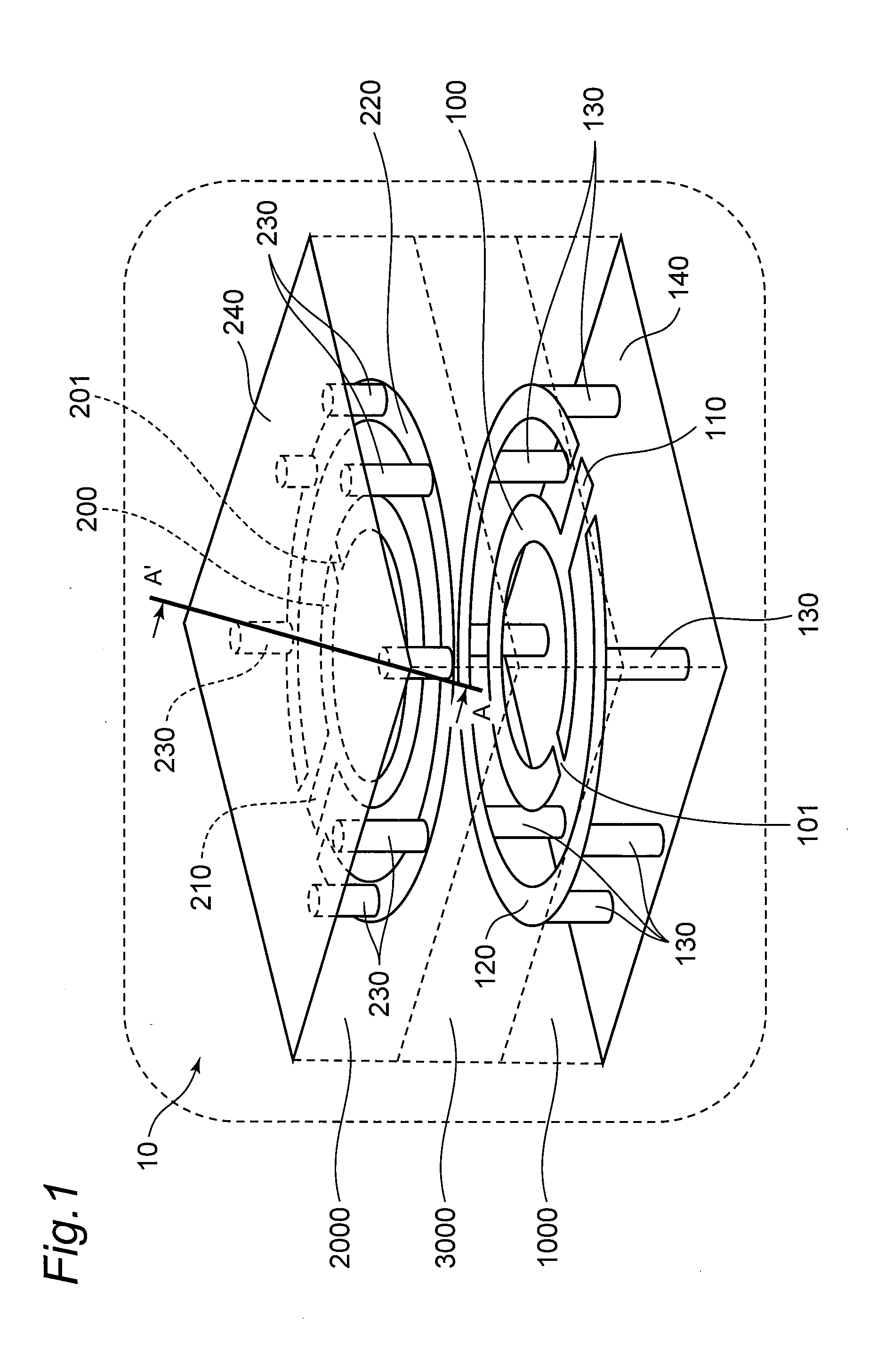
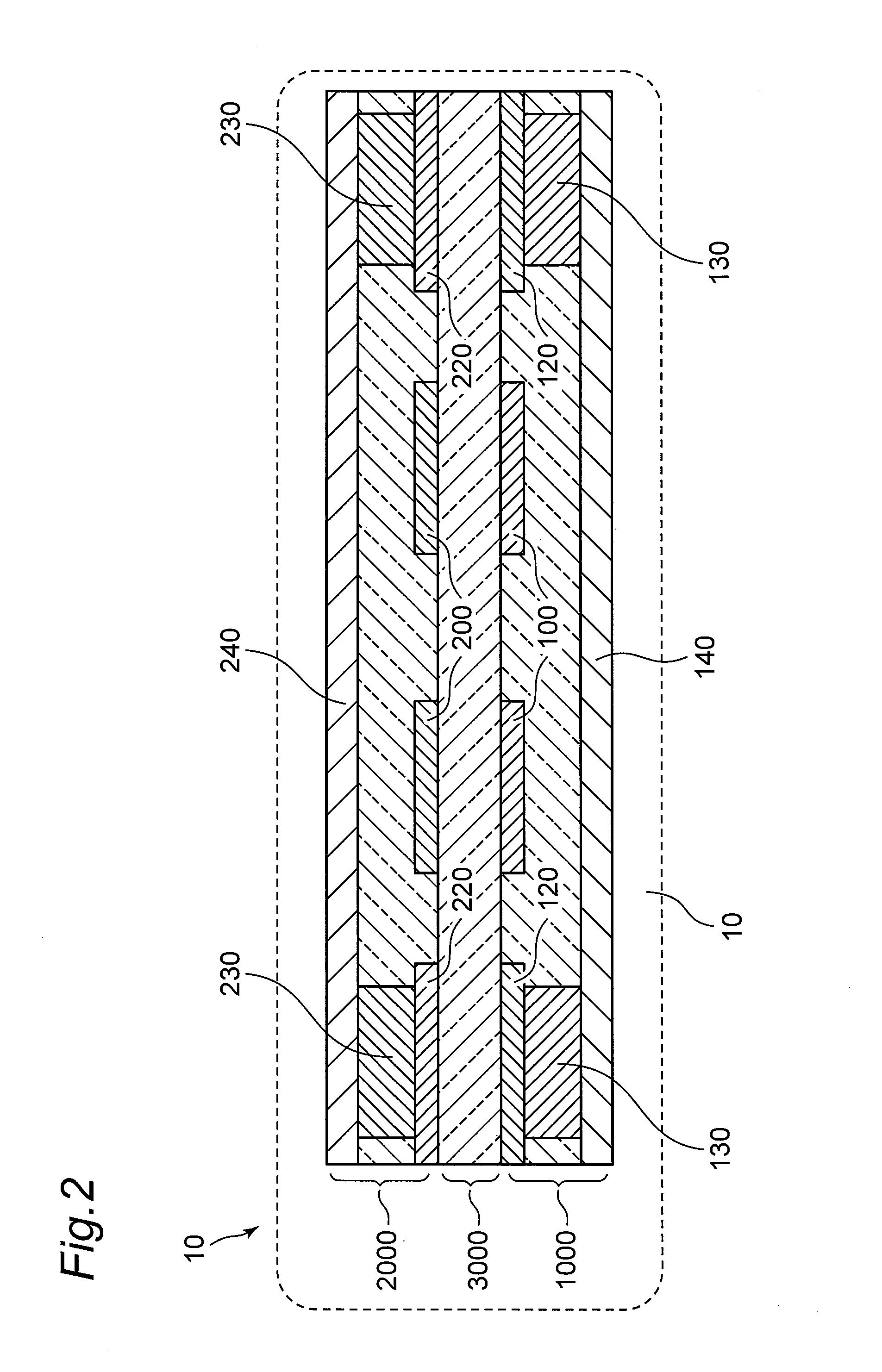
[0203]In the first embodiment of the present invention, the structure of reducing radiation of electromagnetic noise in a lateral direction by arranging the ground wires 120 and 220 in the periphery of the electromagnetic resonant coupler 10 is described.
[0204]On the other hand, an electromagnetic resonant coupler 11 according to a second embodiment of the present invention includes: a first ground wall 330 which extends in a perpendicular direction in a direction from a first ground shield to a second ground shield so as to surround a periphery of a first resonant wire 100; and a second ground wall 430 which extends in a perpendicular direction in a direction from a second ground shield to the first ground shield so as to surround a periphery of a second resonant wire at a position different from the first ground wall 330. The first ground shield and the first ground wall 330 are electrically connected to each other, and the second ground shield and the second ground wall 430 are e...
third embodiment
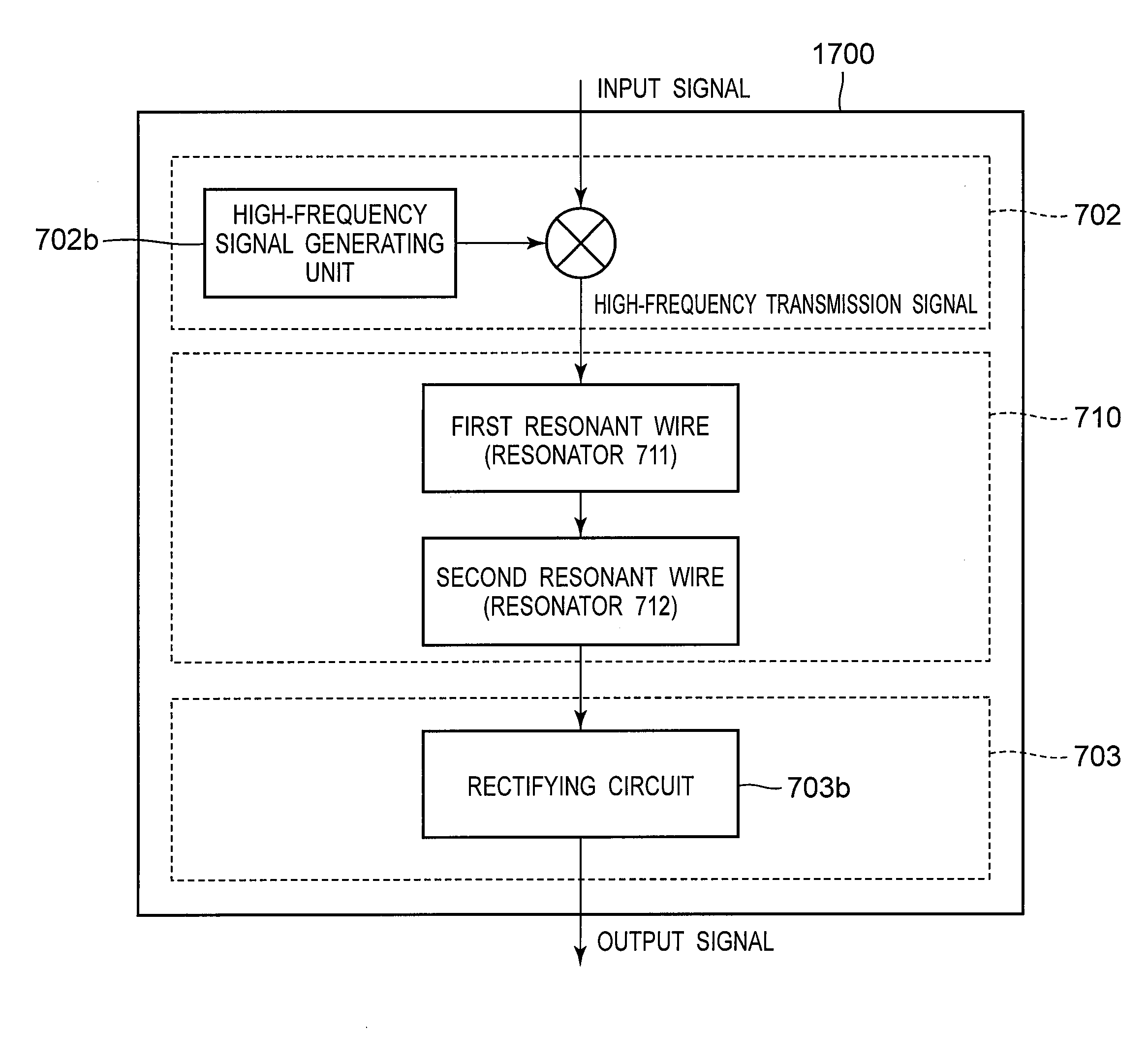
[0240]In the first and second embodiments of the present invention, there are described the electromagnetic resonant coupler 10, 11, and 12 having structures of arranging shields in the lateral direction in order to suppress electromagnetic field noise. On the other hand, in a power transmission device including an electromagnetic resonant coupler according to a third embodiment of the present invention, functional circuit elements are installed on upper parts of the electromagnetic resonant couplers 10, 11, and 12 according to the first or second embodiment so that the functional circuit elements are integrated as a power transmission device.
[0241]Hereinafter, a case of applying the electromagnetic resonant coupler 10 according to the first embodiment of the present invention to a power transmission device 50 will be described as a representative example with reference to drawings.
[0242]FIG. 12 is an example of a perspective view of the power transmission device 50 as an example of...
PUM
 Abstract
Description
Claims
Application Information
 - R&D Engineer
- R&D Manager
- IP Professional
- Industry Leading Data Capabilities
- Powerful AI technology
- Patent DNA Extraction
Browse by: Latest US Patents, China's latest patents, Technical Efficacy Thesaurus, Application Domain, Technology Topic, Popular Technical Reports.
© 2024 PatSnap. All rights reserved.Legal|Privacy policy|Modern Slavery Act Transparency Statement|Sitemap|About US| Contact US: help@patsnap.com