Fan for cooling tower

Inactive Publication Date: 2016-03-17
GEA BATIGNOLLES TECH THERMIQUES
View PDF2 Cites 3 Cited by
  • Summary
  • Abstract
  • Description
  • Claims
  • Application Information

AI Technical Summary

Benefits of technology

[0011]The objective of the invention is to overcome these drawbacks by proposing an industrial

Problems solved by technology

It is also known that the effectiveness of a fan can be impaired by an air recirculation phenomenon that can occur at the base of each blade when there is sufficient space between the hub and the base of the blades to allow air circulation from the pressure face of the blade to the suction surface of the blade.
The overall efficiency of the fan is thus reduced because the air velocity profile is not homogeneous.
Because of this air recirculation phenomenon, about one third of the surface of the blade cannot be charged with air and is made useless.
It is also known that the fans generate a lot of noise.
A source of noise in fans is due to

Method used


Image

  • Fan for cooling tower
  • Fan for cooling tower
  • Fan for cooling tower

Examples


Embodiment Construction

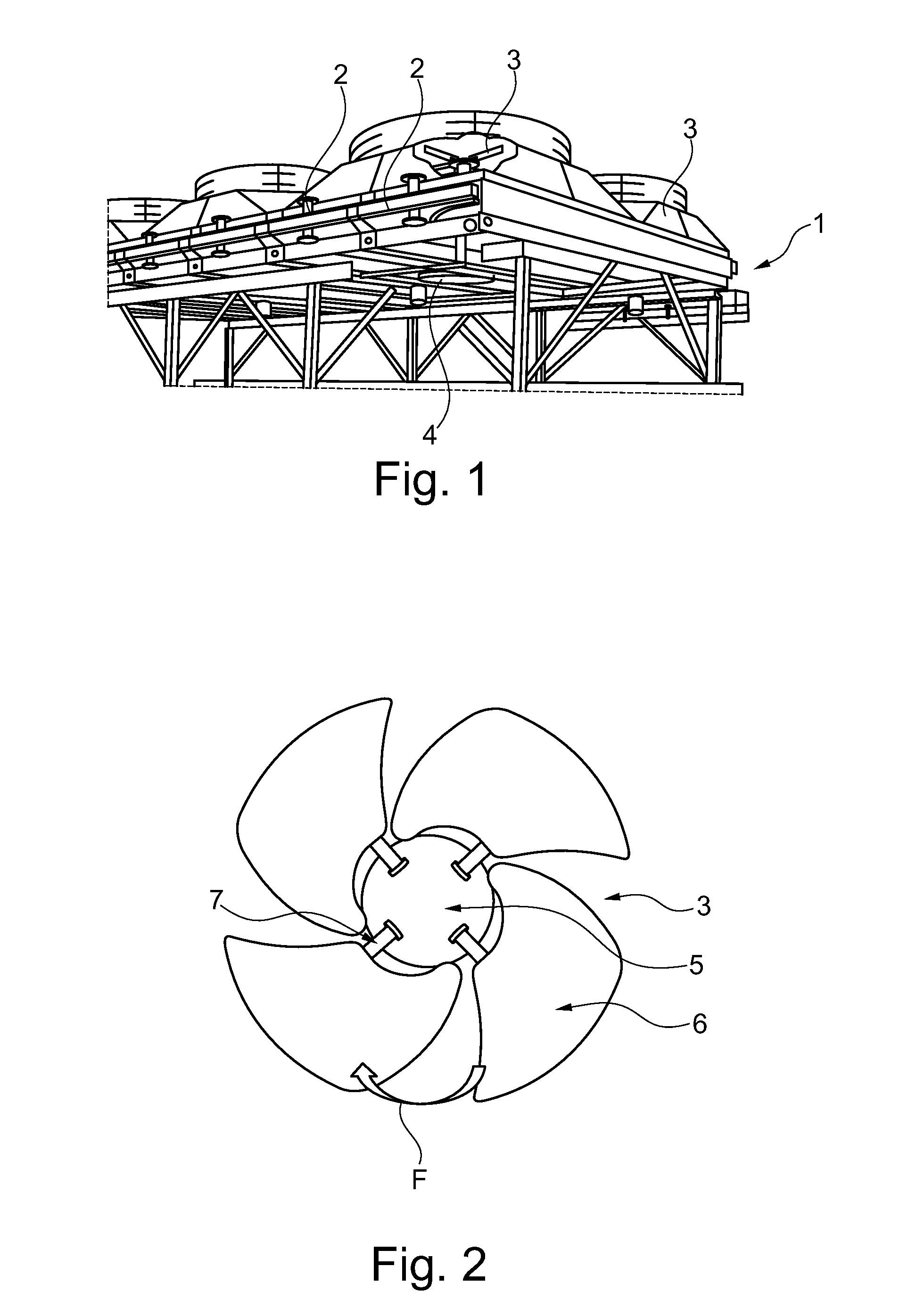
[0035]In FIG. 1, it is illustrated an example of a cooling tower used in oil, gas and chemical industries. In this Figure, an air heat exchanger 1 condenses and cools liquids circulating in finned tube bundles 2. The finned tube bundles 2 are installed on a structure and they are blown by at least one fan 3 actuated by electric motors 4.

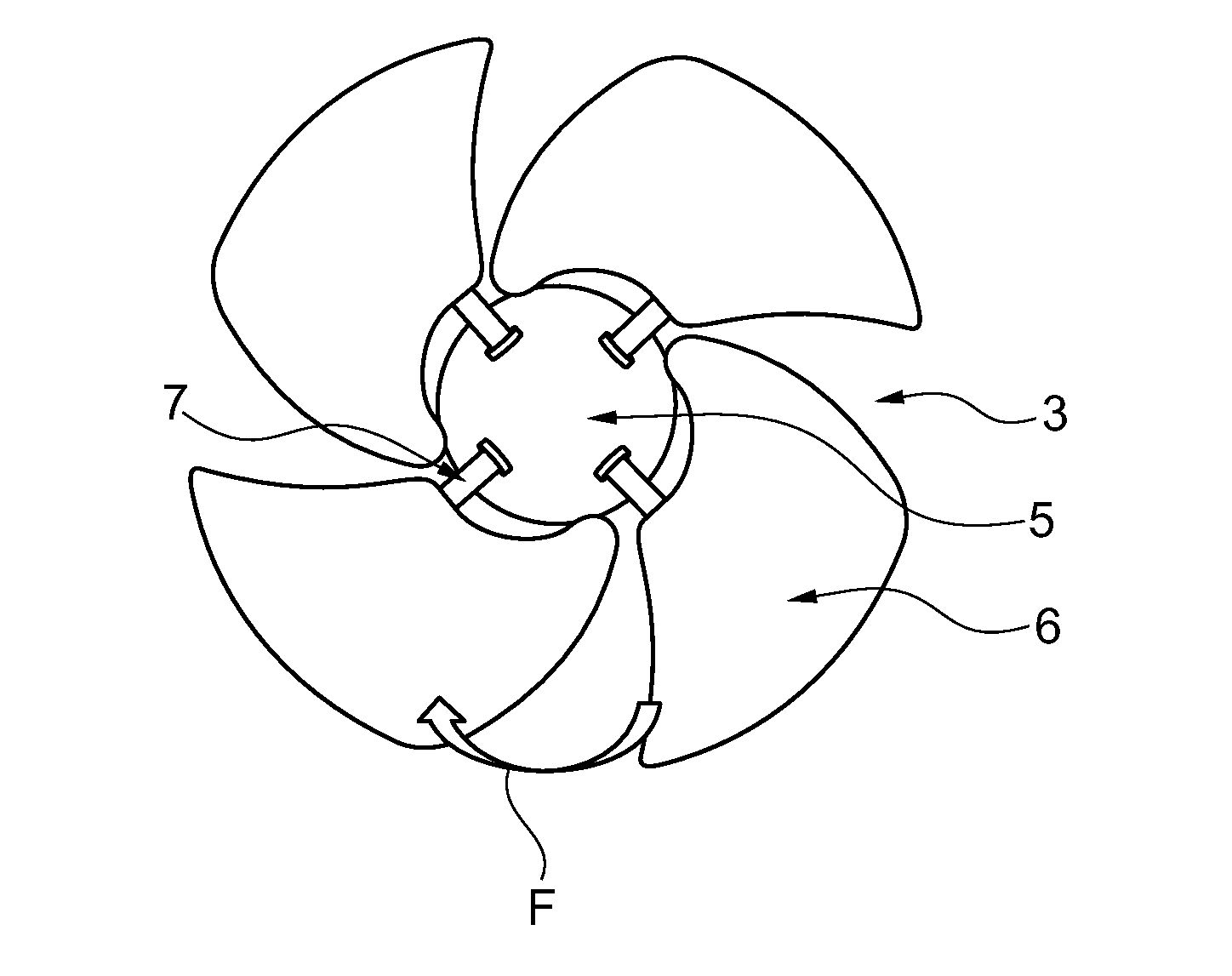
[0036]FIG. 2 illustrates an industrial fan 3 for a cooling tower according to the prior art. This fan 3 includes a disc-shaped hub 5 and a plurality of blades 6 radially connected to the hub disc 5 by means of a stud 7 provided on one end of each blade 6 and a flange (not shown) provided on one side of the hub disc 5 and into which the stud 7 of the blade 6 is inserted with a blade angle for generating an axial air flow.

[0037]The arrow F indicates the direction of rotation of the blades 6.

[0038]The blades 6 have a curvature at the leading and trailing edges, particularly the leading edges have a sweep forward angle of the front ends of the blades rel...


PUM


Abstract

An industrial fan for a cooling tower comprises a disc-shaped hub and a plurality of blades radially connected to the disc of the hub by means of a stud, provided on one end of each said blade, and a flange provided on one face of the hub and into which the stud of the blade is inserted with a blade angle for generating an axial air flow, each blade has such an aerodynamic profile that the pressure difference between pressure and suction faces is lower at the blade foot than at the middle of the blade chord and is higher at the blade head than at the middle of the blade chord, and it is provided a junction means for blocking the air recirculation between the pressure and suction faces at the blade foot.

Description

CROSS-REFERENCE TO RELATED APPLICATIONS[0001]This application claims benefit of French patent application number 1458534, filed Sep. 11, 2014, which is herein incorporated by reference.FIELD OF THE INVENTION[0002]The invention relates to an industrial fan for cooling tower, comprising a disc-shaped hub and a plurality of blades radially connected to the hub disc by means of a stud provided on one end of each blade and a flange provided on a face of the hub and into which the stud of the blade is inserted.[0003]Such a fan is used for example in oil, gas and chemical industries. For example, it can be used in an air heat exchanger for condensing and cooling liquids, such as liquefied natural gas, circulating in finned tube bundles. The finned tube bundles are installed on a structure and they are blown by at least one fan of this type operated by electric motors.BACKGROUND OF THE INVENTIONDescription of the Related Art[0004]Such an industrial fan is notably disclosed in Patent Documen...

Claims


Application Information

Patent Timeline
IPC IPC(8): F04D19/00F04D29/02F04D29/38F04D29/58F04D29/66
CPCF04D19/002F04D29/023F04D29/663F04D29/582F04D29/384F04D25/166F04D29/36F04D29/666F05D2300/43F05D2300/603
Inventor ARNOLD, JACQUESDERUELLE, AURELIEN
Owner GEA BATIGNOLLES TECH THERMIQUES
Why Eureka
Try Eureka