Side-Feed Forced-Air Biomass Burning Cookstove

a biomass burning and sidefeed technology, applied in the direction of domestic stoves or ranges, heating types, lighting and heating apparatus, etc., can solve the problems of poor durability and performance, limited impact of these programs, etc., to reduce particulate emissions, reduce emissions, and increase the thermal efficiency of biomass combustion devices

Inactive Publication Date: 2016-03-17
COLORADO STATE UNIVERSITY +1
View PDF4 Cites 9 Cited by
  • Summary
  • Abstract
  • Description
  • Claims
  • Application Information

AI Technical Summary

Benefits of technology

[0042]Disclosed herein are systems and devices for reducing emissions from biomass combustion devices (e.g. stoves). The disclosed systems and devices may include an exhaust gas recirculation system (EGR) and/or fresh air injection system that reduces particulate emissions. The disclosed systems and devices may also be used to increase thermal efficiency of the biomass combustion devices (e.g., stoves). In many embodiments where exhaust gas is used for injection, a fraction of the...

Problems solved by technology

Though there have been decades of improvements in stove programs, the impact of these programs has been limited due to poor durability and performance, or a lack of understanding of the market such as price point, mi...

Method used


Image

  • Side-Feed Forced-Air Biomass Burning Cookstove
  • Side-Feed Forced-Air Biomass Burning Cookstove
  • Side-Feed Forced-Air Biomass Burning Cookstove

Examples


example ii

EGR—Analysis of PM Emissions Reductions

[0087]The embodiment of FIG. 7 was used to perform initial testing of exhaust gas recirculation. Specifically, particulate matter (PM2.5) was measured during these tests to test for effective emissions reduction. The tests analyzed several variables—for example: Temperature of recirculated exhaust gas, Exhaust gas composition, Exhaust gas injection location and nozzle configuration, and Exhaust gas flow rate.

Recirculated Gas Composition

[0088]To ensure that the amount of ambient air drawn into the EGR pot skirt was minimized, two sets of water boiling tests (WBTs) were run with consistent EGR flow rates, injection locations and nozzle configurations, but with different configurations of the inlets: one set was performed with a ring device as described above, and a second set of data was collected using a conduit that drew exhaust directly from the center of the combustion chamber outlet. This second configuration ensured that all or nearly all g...

example iii

Analysis of Variables Involved in EGR Emissions Reductions

[0109]In the tests described in the previous section, it was shown that emissions reduction can be achieved through the application of EGR. The present section uses similar tests to identify, isolate, and measure various mechanisms affecting emissions reduction observed with EGR through the side injection nozzles.

Testing Platform

[0110]The M5000 was again used for these tests, however, the EGR stove testing platform was modified from that described above. First, conduit was routed such that gas could be injected into the M5000 from compressed gas cylinders. The flow rate of the injected gases was regulated through a high performance Alicat Mass Flow Controller.

Testing Methodology

[0111]It was hypothesized that the reduction in PM emissions with the EGR cookstove could be the net result of a combination of the following mechanisms:

[0112]Increased particle residence time;

[0113]Chemical Effects of O2 / CO2;

[0114]Mixing;

[0115]Dilutio...

example iv

Comparison of EGR with Air Injection

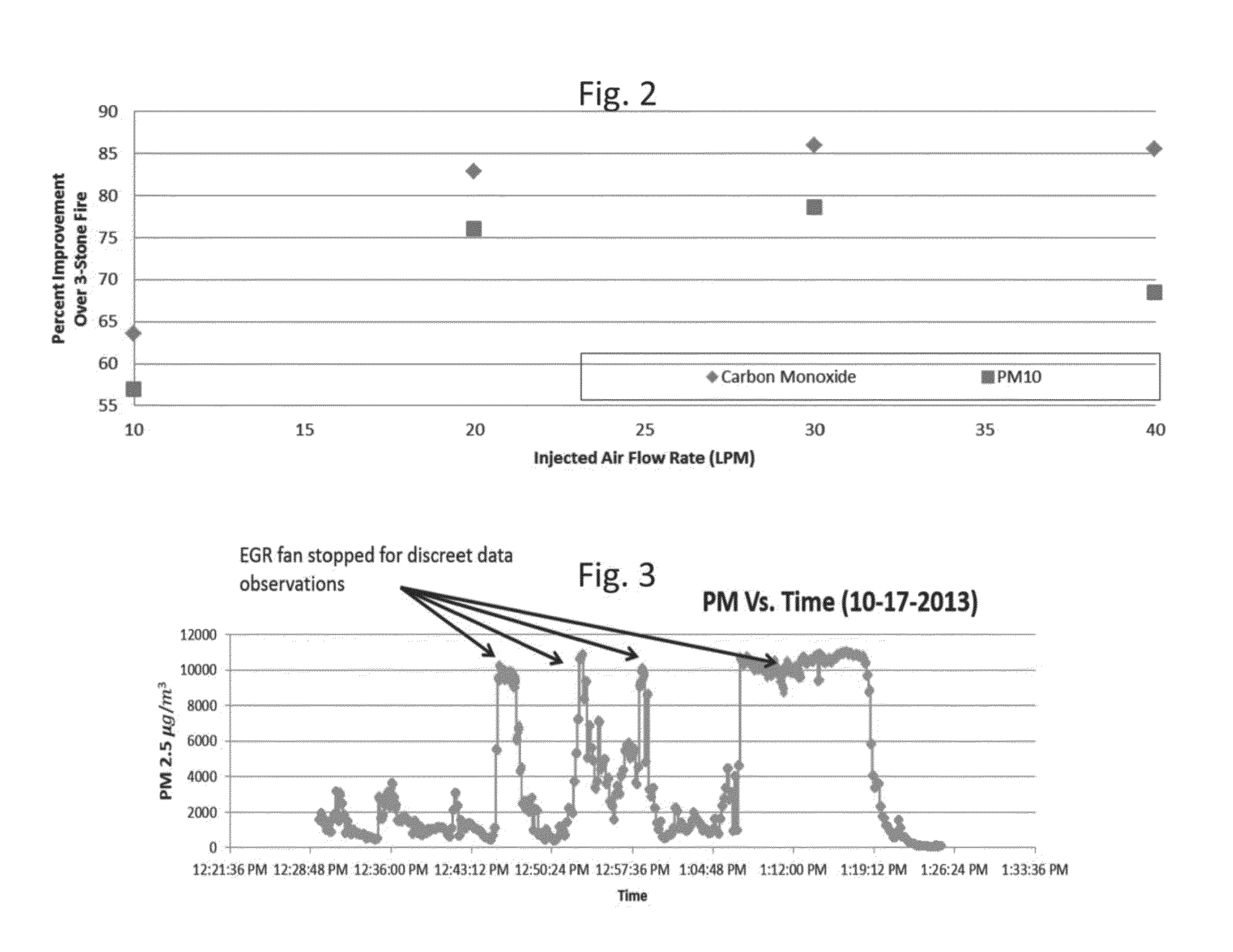
[0149]It was found that one of the primary mechanisms for emissions reduction in the EGR stove was the chemical effect of O2 when injected into the oxidation region of the flame. These results indicate that a stove that utilizes air injection in a similar fashion as the EGR stove side injection nozzles configuration may lead to similar or greater emissions reductions. A study was conducted to confirm this hypothesis, and to understand the relative impacts between the two fundamentally different forced draft systems.

Testing Methodology

[0150]The M5000 was used for these tests. For the forced draft air injection system, compressed air regulated by an Alicat Mass Flow Controller was routed through the side injection nozzles. The side injection nozzles were the same as those used above, with 12 holes at 4.9 millimeter diameter that inject air perpendicularly to the natural draft of the stove at the top of the combustion chamber.

[0151]In order to make a...


PUM


Abstract

Disclosed herein are systems and devices that aid in reducing particulate emissions from biomass stoves, for example by the use of gases injected in or near the oxidation zone of a combustion chamber. Also disclosed are systems and devices providing electricity to a pump or blower that aids in injecting the gas and/or collecting exhaust gases. In some embodiments the device providing electricity is a thermoelectric generator that may also be used to power other devices. In many embodiments, the systems and devices inject a gas at or near the oxidation zone in the combustion chamber of a biomass stove. The gas injected into the zone may be fresh air, exhaust from combustion or combinations thereof. The gas can be forced into the to combustion chamber with the aid of a pump or blower that may also aid in drawing in exhaust gas.

Description

CROSS REFERENCE TO RELATED APPLICATIONS[0001]This application claims benefit of priority pursuant to 35 U.S.C. §119(e) of U.S. provisional patent application No. 62 / 048,884, filed on Sep. 11, 2014, which is incorporated herein by reference in its entirety.FIELD[0002]The present disclosure systems and devices that aid in reducing emissions from biomass stoves, for example by the use of gases injected into the combustion chamber at or near the oxidation zone. Also disclosed are systems and devices for generating electricity from a biomass stove to operate a pump or blower that aids in injecting the gas and / or collecting exhaust gases.BACKGROUND OF THE INVENTION[0003]The global commercial market for improved cookstoves is a nascent one. Though there have been decades of improvements in stove programs, the impact of these programs has been limited due to poor durability and performance, or a lack of understanding of the market such as price point, misplaced subsidies, lack of promotion ...

Claims


Application Information

Patent Timeline
IPC IPC(8): F24B5/02F24B1/02
CPCF24B1/028F24B5/028F23B50/00F23B50/02F23B50/04F23B50/10F23B50/12F23B80/02F23B2700/013F23M2900/13003
Inventor DEFOORT, MORGAN W.LORENZ, NATHANMIZIA, JOHNPRAPAS, JASONDISCHINO, KEVIN
Owner COLORADO STATE UNIVERSITY
Why Eureka
Try Eureka