This helps you quickly interpret patents by identifying the three key elements:
Problems solved by technology
Method used
Benefits of technology
Benefits of technology
This patent is about a new type of wire used for electronic devices. The wire has a special structure that makes it easier to bond with other components. The wire also has a specific stiffness that ensures good contact and performance. The wire has a core made of pure copper, with a low amount of impurities like boron and phosphorus. By controlling these impurities, the wire can have improved properties and reliability. The patent also mentions that the wire should have a minimum strength of 75 GPa or higher to ensure good performance.
Moreover, copper wires are susceptible to oxidation.
However, bending of the ribbons is limited and orientation of the ribbon must be observed when bonding in order to arrive at acceptable electrical contact between the ribbon and the element to which it is bonded.
However, bonding involves welding and larger deformation of the wire in the bonding process, which can cause harm or even destroy the bond pad and underlying electric structures of the element which is bonded thereto.
Method used
Image
Click on the blue label to locate the original text in one second.
Reading with bidirectional positioning of images and text.
Examples
example 1
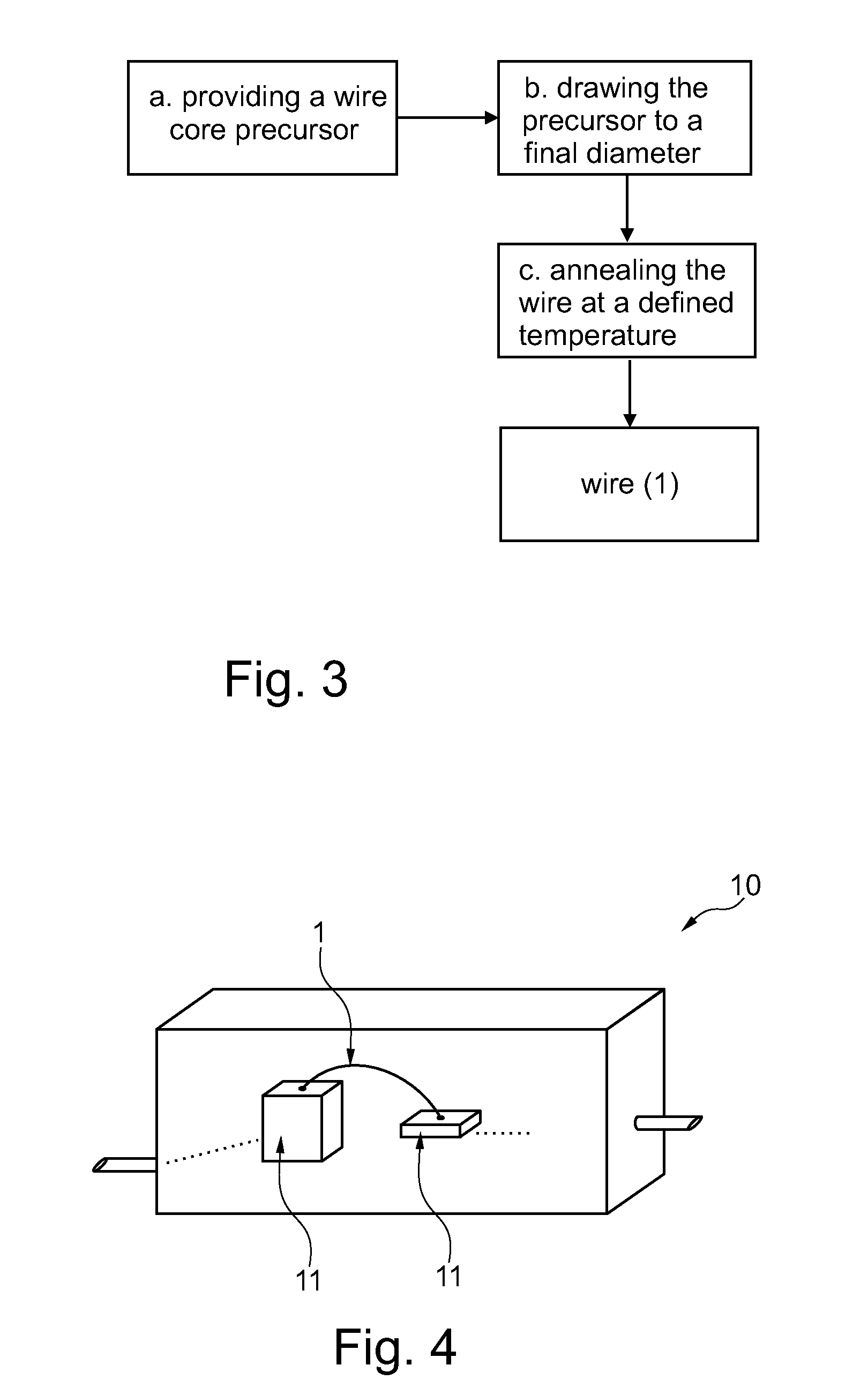
[0113]A quantity of copper material of at least 99.99% purity (“4N-copper”) was molten in a crucible. No further substances were added to the melt. Then a wire core precursor was cast from the melt.
[0114]The chemical composition of the Cu wire was controlled using an Inductively Coupled Plasma (ICP) instrument (Perkin Elmer ICP-OES 7100DV). The Cu wires were dissolved in concentrated nitric acid and the solution was used for ICP analysis. The methodology to test highly pure Cu wire was established with the equipment manufacturer as per the well-known technique adopted for bulk Cu.
[0115]The wire core precursor was then drawn in several drawing steps to form the wire core 2 with a specified diameter. In order to confirm the beneficial effects of the invention for different diameters, a selection of wires with different diameters have been manufactured. Table 1 below shows a list of the different wire diameters:
TABLE 1Ranges of elongation and average grain sizes for different wire diam...
example 2
[0143]A quantity of copper material of at least 99.99% purity (“4N-copper”) is molten in a crucible. Small amounts of silver (Ag) are added to the melt and an even distribution of the added components in the copper melt is provided. Then a wire core precursor is cast from the melt.
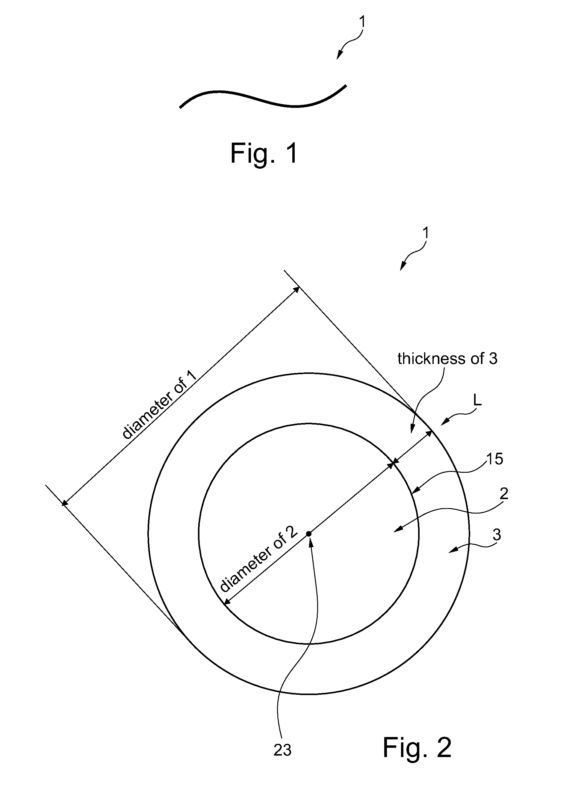
[0144]The wire core precursor is then drawn in several drawing steps to form the wire core 2 with a specified diameter of presently 20 μm. The cross section of the wire core 2 is of essentially circular shape. It is to be understood that the wire diameter is not considered a highly exact value due to fluctuations in the shape of the cross section or the like. In the present sense, if a wire is defined to have a diameter of e.g. 20 μm, the diameter is understood to be in the range of 19.5 to 20.5 μm.
[0145]By this procedure, several different samples of an inventive wire and a comparative wire have been manufactured.
[0170]A quantity of copper material of at least 99.99% purity (“4N-copper”) is melted in a crucible. Small amounts of palladium (Pd) are added to the melt and an even distribution of the added component in the copper melt is provided. Then a wire core precursor is produced by continuously and slowly casting the melt into rods of between 2 mm and 25 mm diameter.
[0171]The wire core precursor is then drawn in several drawing steps to form the wire core 2 with a specified diameter of presently 20 μm. The drawing is conducted as cold drawing at room temperature.
[0172]Concerning the cross section shape of the wire core 2, reference is made to the remarks for the above examples.
[0173]By this procedure, several different samples of an inventive wire have been manufactured. In a first variant, the amount of palladium in the copper has been adjusted to 0.89%. In a second, most preferred variant, the amount of palladium has been adjusted to 1.25%.
[0174]Concerning thresholds of impurities of fu...
PUM
Property
Measurement
Unit
Temperature
aaaaa
aaaaa
Temperature
aaaaa
aaaaa
Momentum
aaaaa
aaaaa
Abstract
The invention is related to a bonding wire containing a core having a surface. The core contains copper as a main component, an average size of crystal grains in the core is between 2.5 μm and 30 μm, and a yield strength of the bonding wire is less than 120 MPa.
Description
CROSS-REFERENCE TO RELATED APPLICATIONS[0001]This application is a Section 371 of International Application No. PCT / SG2014 / 000151, filed Apr. 4, 2014, which was published in the English language on Nov. 6, 2014 under International Publication No. WO 2014 / 178792 A1 and the disclosure of which is incorporated herein by reference.BACKGROUND OF THE INVENTION[0002]Bonding wires are used in the manufacture of semiconductor devices for electrically interconnecting an integrated circuit and a printed circuit board during semiconductor device fabrication. Further, bonding wires are used in power electronic applications to electrically connect transistors, diodes and the like with pads or pins of the housing. While bonding wires were originally made from gold, nowadays less expensive materials, such as copper, are used. While copper wire provides very good electric and thermal conductivity, ball-bonding and wedge-bonding of copper wire have challenges. Moreover, copper wires are susceptible t...
Claims
Application Information
Patent Timeline
Application Date:The date an application was filed.
Publication Date:The date a patent or application was officially published.
First Publication Date:The earliest publication date of a patent with the same application number.
Issue Date:Publication date of the patent grant document.
PCT Entry Date:The Entry date of PCT National Phase.
Estimated Expiry Date:The statutory expiry date of a patent right according to the Patent Law, and it is the longest term of protection that the patent right can achieve without the termination of the patent right due to other reasons(Term extension factor has been taken into account ).
Invalid Date:Actual expiry date is based on effective date or publication date of legal transaction data of invalid patent.

