
Fcc units, apparatuses and methods for processing pyrolysis oil and hydrocarbon streams

a technology of fluid catalytic cracking and pyrolysis oil, which is applied in the direction of lighting and heating apparatus, fuels, etc., can solve the problems of pyrolysis oil feed lines being clogged, adding unit operations, and added capital costs to the upgrading process, and fcc processing is particularly prone to clogging

Inactive Publication Date: 2016-03-31
UOP LLC
View PDF1 Cites 13 Cited by
  • Summary
  • Abstract
  • Description
  • Claims
  • Application Information

AI Technical Summary

Benefits of technology

The patent describes a method and apparatus for converting a mixture of pyrolysis oil and hydrocarbon into fuel. This involves using a fluid catalytic cracking unit that has a reaction chamber, a coolant conduit, and a pyrolysis oil conduit. The method involves introducing the hydrocarbon stream into the reaction zone and injecting the pyrolysis oil into the coolant stream. The technical effect of this patent is the efficient and effective conversion of pyrolysis oil and hydrocarbon into fuel using a fluid catalytic cracking unit.

Problems solved by technology

Such approaches add unit operations, along with added capital costs, to the upgrading process.
Further, even after deoxygenating the pyrolysis oils, pyrolysis oil feed lines may become clogged due to polymerization of the pyrolysis oils, and pyrolysis oil feed lines that facilitate introduction of a pyrolysis oil stream into a reaction zone where FCC processing is conducted are particularly prone to clogging.
Additionally, feed lines that contain mixtures of a hydrocarbon stream and a pyrolysis oil stream are also generally prone to clogging due to the presence of the pyrolysis oil stream in the feed lines.
Simply separating and introducing the hydrocarbon stream and the pyrolysis oil stream into the reaction zone through separate feed lines is ineffective to avoid clogging.

Method used


Image

  • Fcc units, apparatuses and methods for processing pyrolysis oil and hydrocarbon streams
  • Fcc units, apparatuses and methods for processing pyrolysis oil and hydrocarbon streams
  • Fcc units, apparatuses and methods for processing pyrolysis oil and hydrocarbon streams

Examples


Embodiment Construction

[0014]The following detailed description is merely exemplary in nature and is not intended to limit the FCC units, apparatuses, and methods for processing pyrolysis oil and hydrocarbon streams. Furthermore, there is no intention to be bound by any theory presented in the preceding background or the following detailed description.

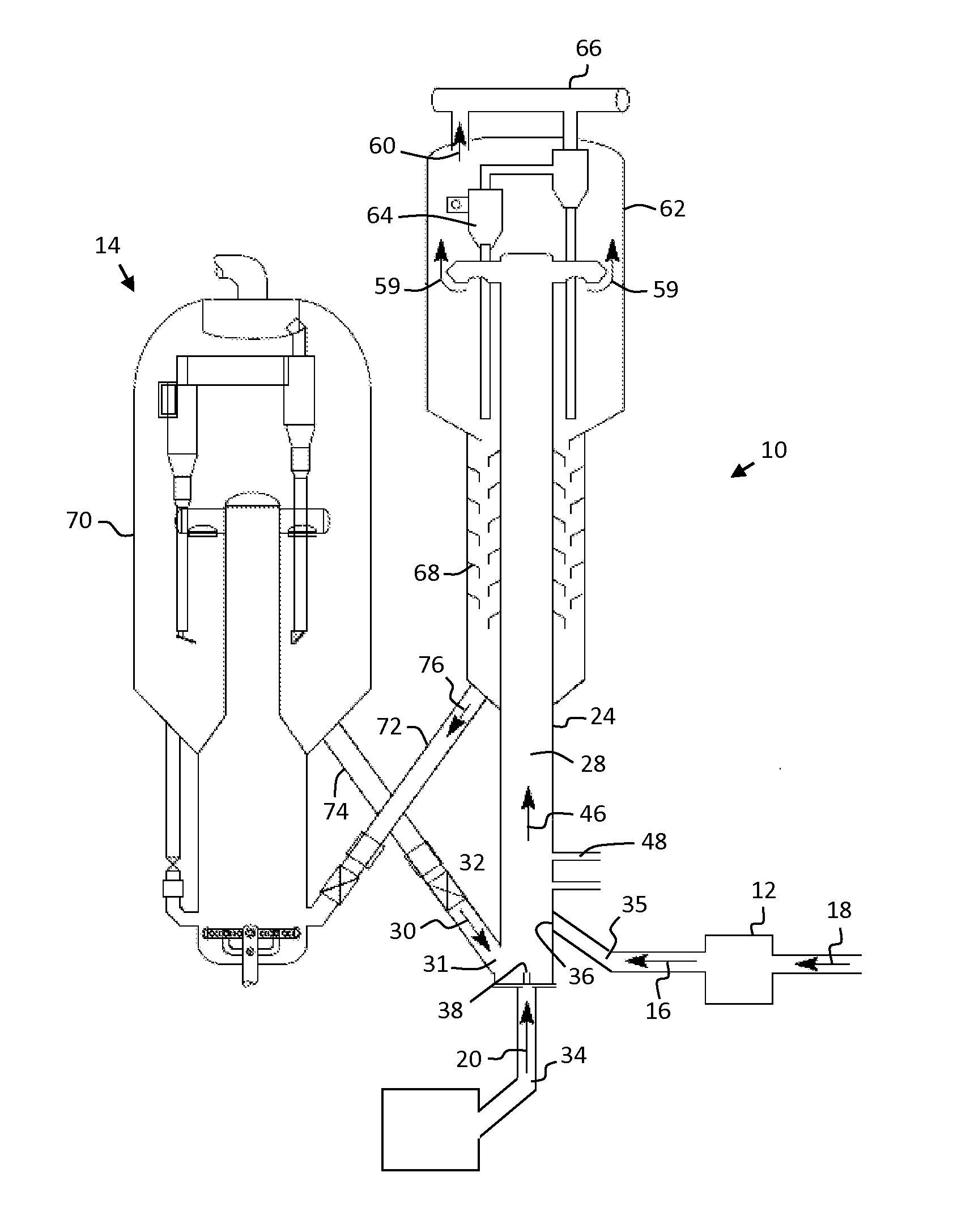
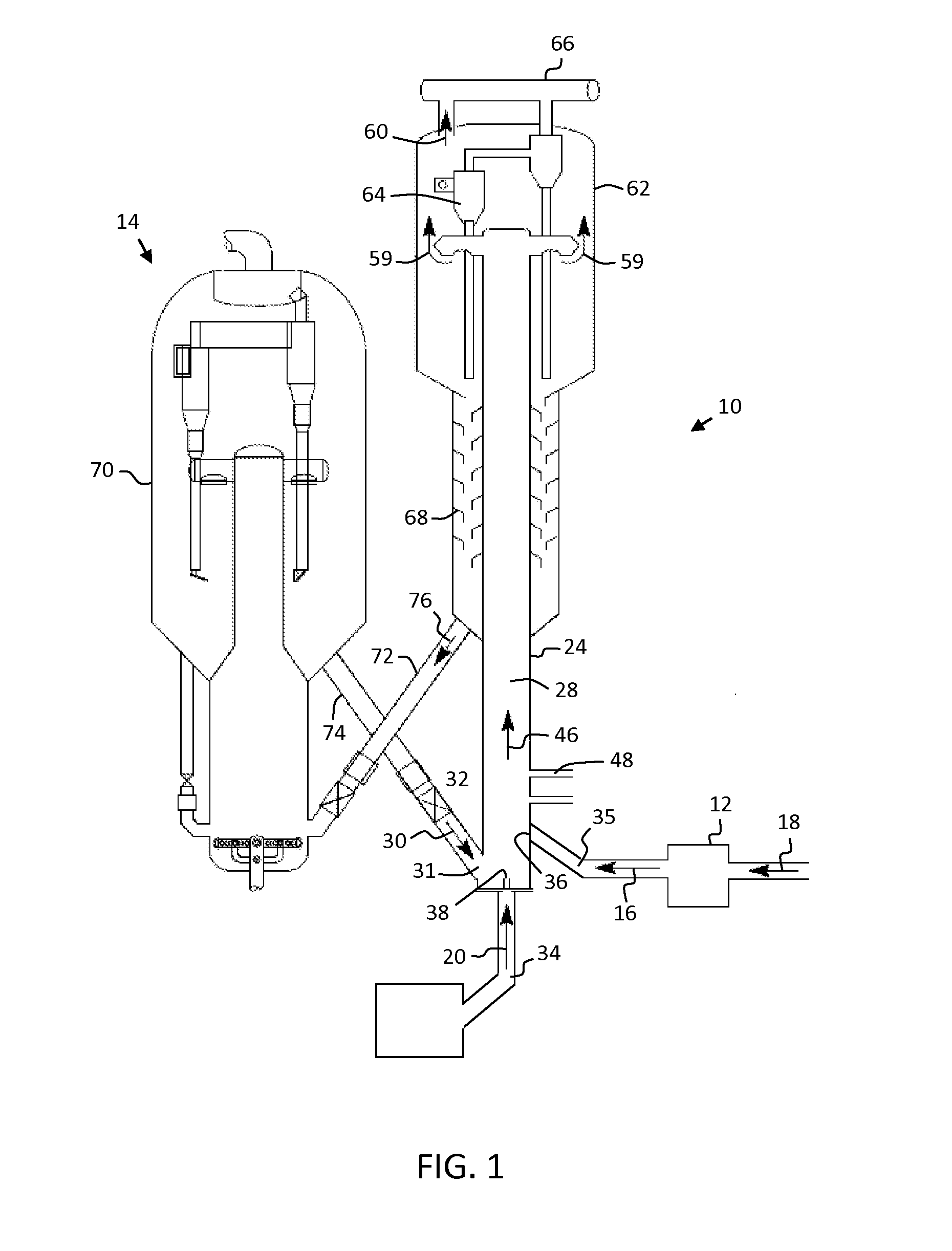
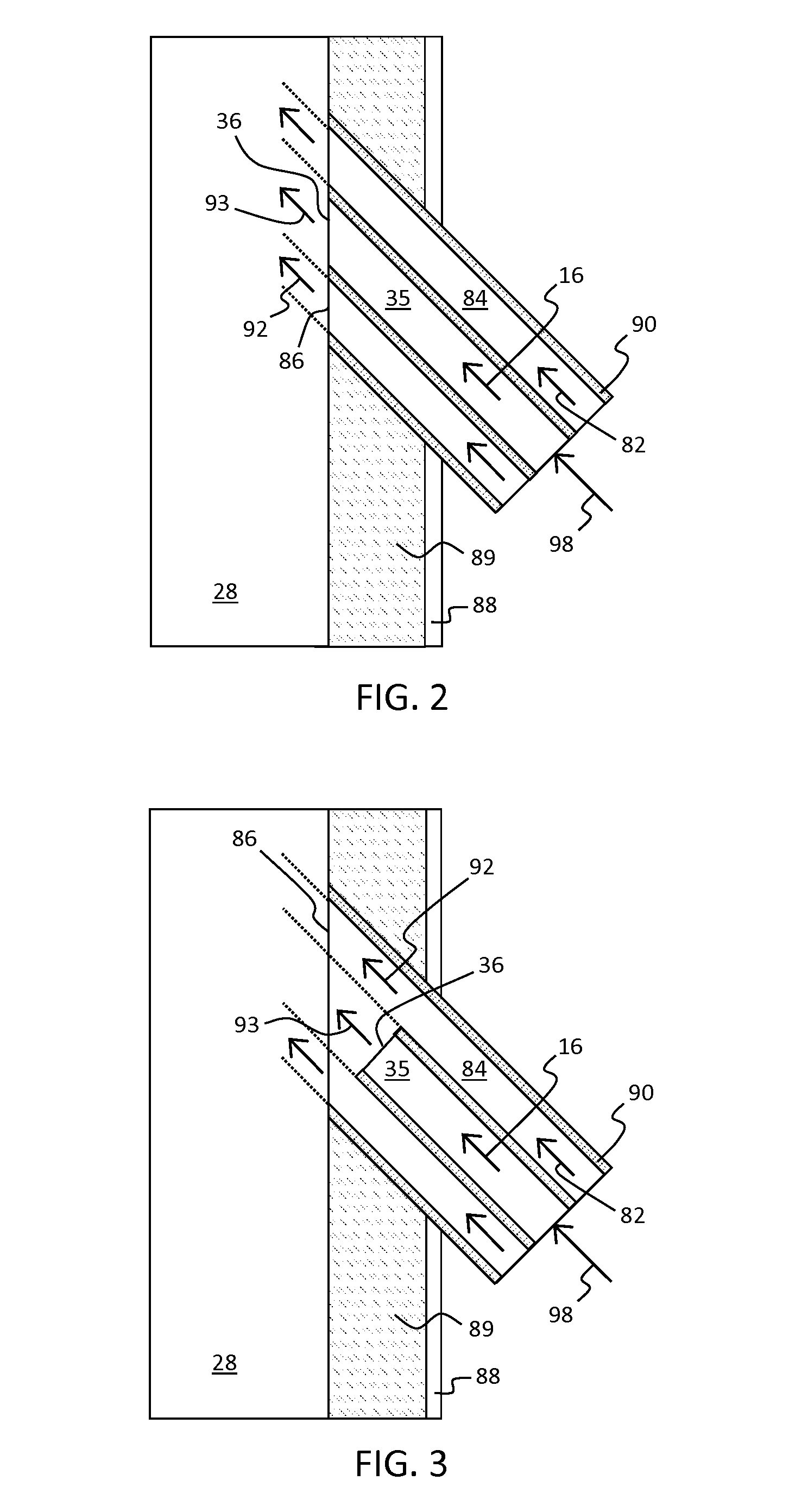
[0015]FCC units, apparatuses and methods for processing pyrolysis oil and hydrocarbon streams are provided herein. In exemplary embodiments, the processing involves upgrading the pyrolysis oil stream and the hydrocarbon stream. As referred to herein, “upgrading” refers to conversion of relatively high boiling point hydrocarbons to lower boiling point hydrocarbons. Upgrading processes generally render the hydrocarbon stream and the pyrolysis oil stream suitable for use as a transportation fuel. In the methods and fuel processing apparatuses described herein, a mixture of the pyrolysis oil stream and the hydrocarbon stream are catalytically cracked in a reacti...


PUM

PropertyMeasurementUnit
Temperatureaaaaaaaaaa

Abstract

Fluid catalytic cracking (FCC) units, apparatuses, and methods for catalytically cracking a mixture of a pyrolysis oil stream and a hydrocarbon stream are provided herein. In an embodiment, an FCC unit includes a reaction chamber suitable for contacting a pyrolysis oil, a hydrocarbon, and a catalyst. The FCC unit includes a coolant conduit having an coolant outlet in communication with the reaction chamber and suitable for introducing a coolant stream through the coolant outlet into the reaction chamber. The FCC unit further includes a pyrolysis oil conduit including a pyrolysis oil outlet positioned within the coolant conduit and suitable for injecting the pyrolysis oil through the pyrolysis oil outlet into the reaction chamber.

Description

TECHNICAL FIELD[0001]The technical field generally relates to apparatuses and methods for processing pyrolysis oil and hydrocarbon streams. More particularly, the technical field relates to fluid catalytic cracking (FCC) units, apparatuses, and methods for catalytically cracking a mixture of a pyrolysis oil stream and a hydrocarbon stream.BACKGROUND[0002]Fluid catalytic cracking (FCC) is a well-known process for the conversion of relatively high boiling point hydrocarbons to lower boiling point hydrocarbons in the heating oil or gasoline range. Such processes are commonly referred to in the art as “upgrading” processes. To conduct FCC processes, FCC units are generally provided with one or more reaction zones where a relatively high boiling point hydrocarbon stream is contacted with a particulate cracking catalyst. The particulate cracking catalyst is maintained in a fluidized state under conditions that are suitable for the conversion of the relatively high boiling point hydrocarbo...

Claims


Application Information

Patent Timeline
IPC IPC(8): C10G11/18B01J8/18C10L1/04
CPCC10G11/182C10L1/04B01J2208/00902C10L2200/0469B01J2208/00176B01J8/1836B01J8/1827B01J8/1863B01J8/1872B01J8/388B01J2208/00362B01J2208/00371C10G11/187
Inventor FREY, STANLEY, JOSEPHGU, WEIKAI
Owner UOP LLC
Learn More