Method for depositing flowable material using alkoxysilane or aminosilane precursor

a technology of flowable materials and precursors, applied in the field of semiconductor techniques, can solve problems such as the inability to prevent post-deposition processes completely, and achieve the effects of reducing film shrinkage, improving chemical resistance in trenches, and reducing carbon conten

Active Publication Date: 2010-11-02
ASM JAPAN
View PDF2 Cites 406 Cited by
  • Summary
  • Abstract
  • Description
  • Claims
  • Application Information

AI Technical Summary

Benefits of technology

[0006]The inventors began evaluating silazane-based materials, such as those having a Si—N skeleton without OH, to establish a technology to ensure flowability while reducing the film shrinkage at the same time (U.S. Patent Application Publication No. 2009/0142935, the disclosure of which is herein incorporated by reference in its entirety). However, in some cases problems occurring in post-deposition processes could not be prevented completely and these problems were suspected to be caused by carbon, just like when siloxane is used. Accordingly, the inventors subsequently reduced the carbon content in the material to reduce the ...

Problems solved by technology

However, in some cases problems occurring in post-deposition processes could not be prevented ...

Method used


Image

  • Method for depositing flowable material using alkoxysilane or aminosilane precursor
  • Method for depositing flowable material using alkoxysilane or aminosilane precursor
  • Method for depositing flowable material using alkoxysilane or aminosilane precursor

Examples


example 1

[0050]To identify a material that allows for achievement of a Si—O state immediately after deposition without causing carbon impurities from being taken into the film, those that do not directly contain Si and hydrocarbon bond were examined. To be specific, an evaluation was conducted to identify whether the amount of carbon impurities taken into the deposited insulation material having flowability could be reduced substantially based on plasma CVD by using a material whose skeleton is Si—O—CH3 or Si—N—CH3 where oxygen or nitrogen is sandwiched between Si and carbon. For the Si-containing precursors not having Si—C bond used in this evaluation, tetramethoxysilane and hexamethoxydisilane were used. For the Si-containing precursor having Si—C bond, monomethyltriethoxysilane was used. The deposition conditions are shown below.

[0051]

TABLE 2DistanceRFbetweenSusceptorPrecursorHe gasO2 gasPressure(13.56 MHz)electrodesTem.[sccm][sccm][sccm][Pa][W][mm][° C.]tetramethoxysilane5010005026650200...

example 2

[0057]To identify a material that allows for achievement of a Si—O state immediately after deposition without causing carbon impurities from being taken into the film, materials that do not directly contain Si and hydrocarbon bond, or specifically tetramethoxysilane containing O—CH3 and tetraethoxysilane containing O—C2H5, were compared. The deposition conditions are as follows.

[0058]

TABLE 4DistanceRFbetweenSusceptorPrecursorHe gasO2 gasPressure(13.56 MHz)electrodesTem. [sccm][sccm][sccm][Pa][W][mm][° C.]Ttramethoxysilane5010005026650200Tetraethoxysilane5010005026650200

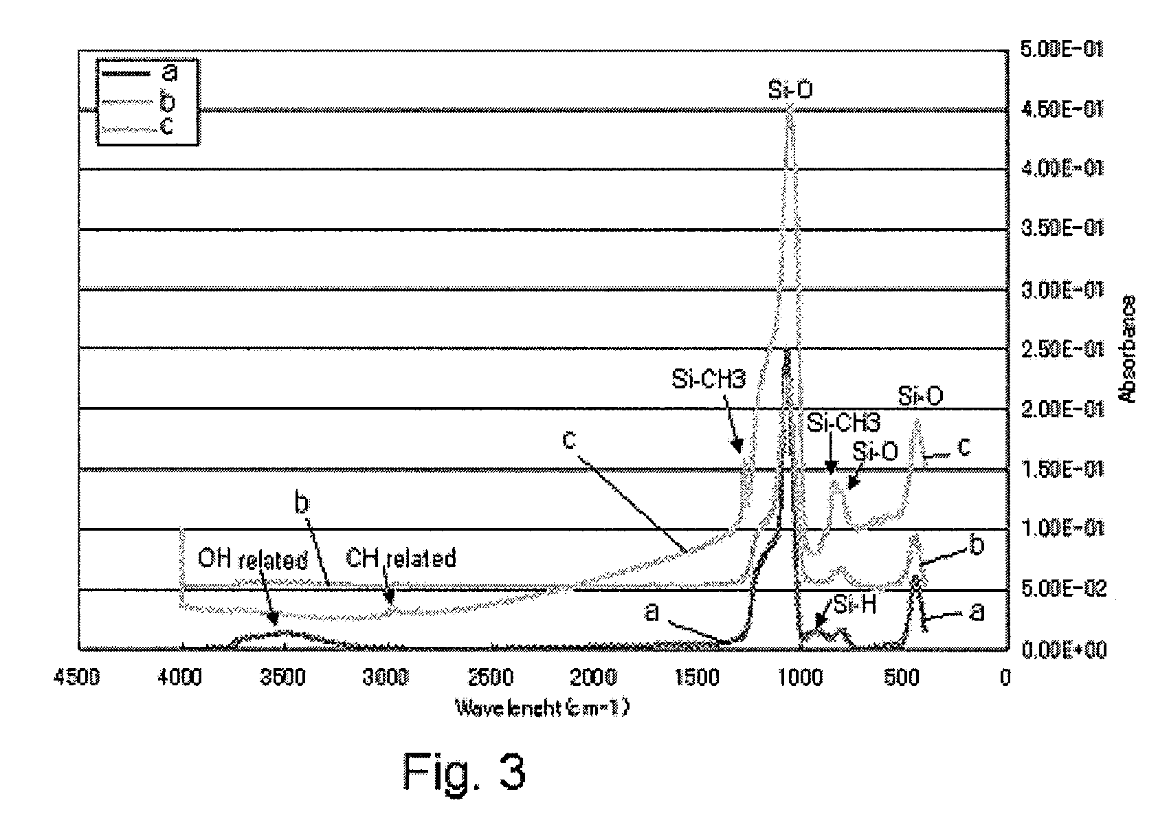
[0059]Results are shown in FIG. 4, which is a FT-IR graph showing the condition of bond in the formed film. In this embodiment, the precursor has a hydrocarbon as the terminal group, where the terminal hydrocarbon is CH3. In addition to CH3, C2H5, C3H7, etc., can be cited as candidate hydrocarbons. As evident from the FT-IR graph in FIG. 4 showing the confirmed condition of carbon content after deposition, adopting CH...

example 3

[0060]To evaluate STI filler oxide films having high-temperature resistance, films were deposited under the process conditions listed below (susceptor temperature: 0° C.).

[0061]In the table, a downward pointing arrow indicates that the immediately overlying entry is carried over to the box containing the arrow.

[0062]

TABLE 5Flow rateO2 flow He flowDischarge Flowabilityof materialrateratePressure13.56 MhzdistancepatternExampleMaterial(sccm)(sccm)(sccm)(Pa)(W)(mm)diagram3-1Hexamethoxydisilane200100026610020B3-2↓↓50↓↓↓↓↓3-3↓↓200↓↓↓↓A3-4↓↓0↓133↓↓B3-5↓50↓↓266↓↓↓3-6Hexaaminodisilane2040↓↓↓↓↓3-7↓2020↓↓↓↓↓3-8Trimethoxysilanol1000↓400↓↓↓3-9↓↓↓↓266↓↓↓ 3-10Hexamethoxydisilane20↓↓↓300↓A

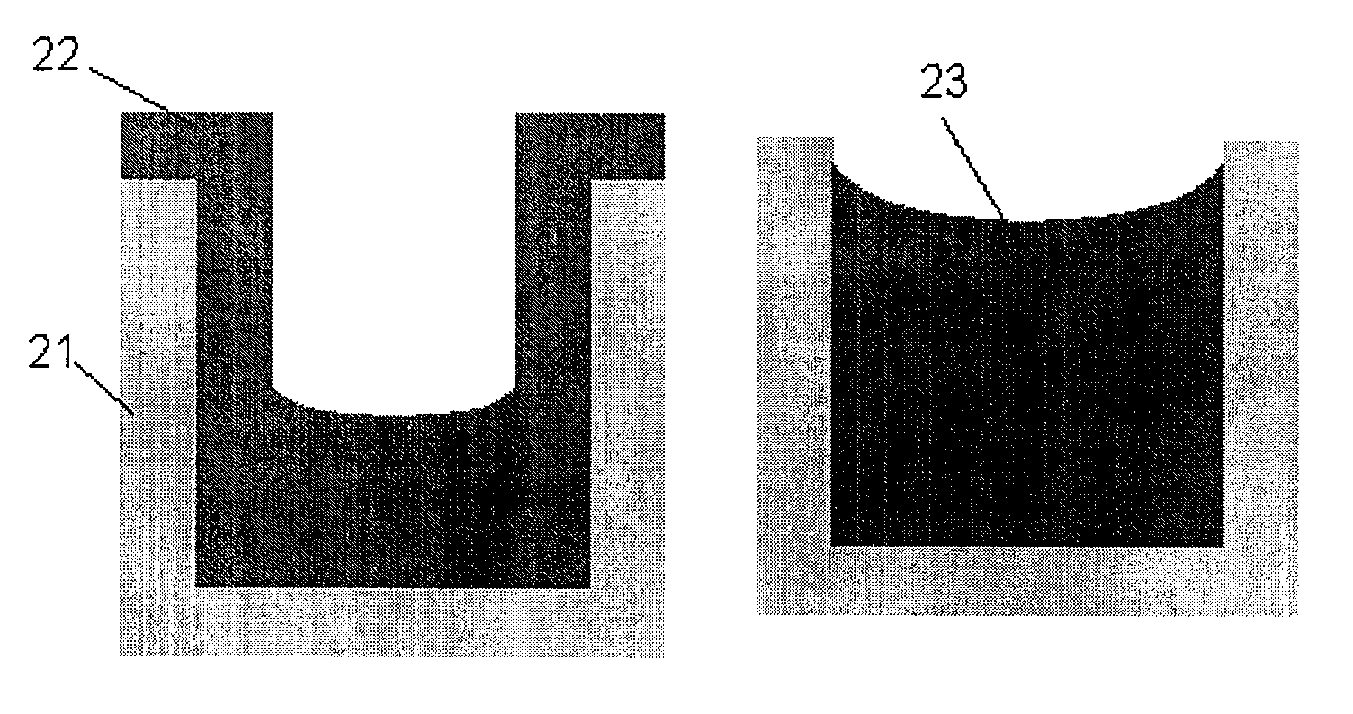
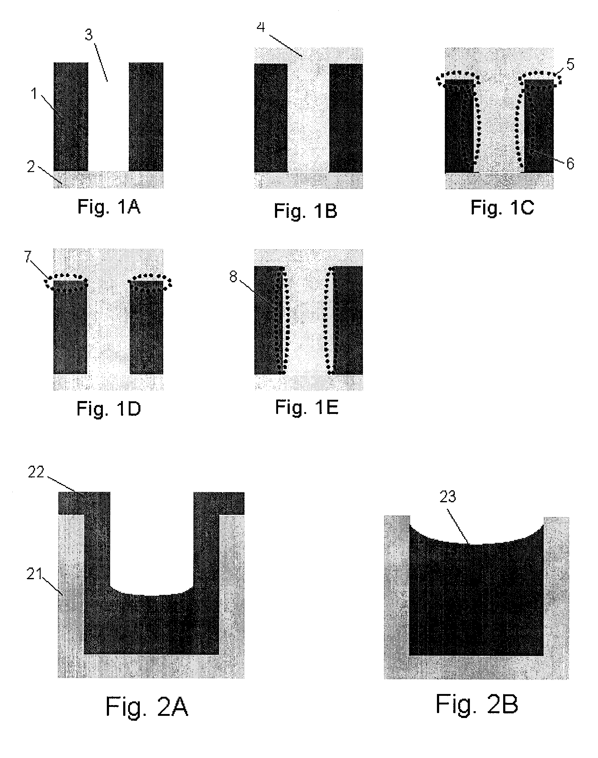
[0063]Additionally, the flowability pattern diagrams indicating in the last column of Table 5 show the results of evaluating chemical resistance in the filled film and pattern based on the Line / Space ratio of 20 / 40 nm, as explained in FIGS. 2A and 2B. In condition A where the viscosity is high (FIG. 2A), flowable ...


PUM

PropertyMeasurementUnit
Temperatureaaaaaaaaaa

Abstract

A method of filling a recess with an insulation film includes: introducing an alkoxysilane or aminosilane precursor containing neither a Si—C bond nor a C—C bond into a reaction chamber where a substrate having an irregular surface including a recess is placed; and depositing a flowable Si-containing insulation film on the irregular surface of the substrate to fill the recess therewith by plasma reaction at −50° C. to 100° C.

Description

BACKGROUND OF THE INVENTION[0001]1. Field of the Invention[0002]The present invention relates generally to a semiconductor technique and more particularly to a method for depositing a flowable material using an alkoxysilane or aminosilane precursor on a substrate having an irregular surface.[0003]2. Description of the Related Art[0004]In recent years, there has been a practice of using a plasma CVD apparatus equipped with a low-temperature susceptor to deposit onto a silicon substrate an insulating liquid material having flowability, after which the deposited material is filled by means of surface tension into trenches of semiconductor circuitry having irregular surface. According to an evaluation of low-temperature plasma CVD using an alkoxide siloxane material having one Si, however, filled shape problems called “voids” occurred in trenches when trenches having irregular surface were completely filled with a material of low flowability (refer to U.S. Patent Laid-open No. 2008 / 0076...

Claims


Application Information

Patent Timeline
IPC IPC(8): H01L21/31
CPCC23C16/401C23C16/56H01L21/02164H01L21/02211H01L21/02219H01L21/02274H01L21/02337H01L21/31608
Inventor FUKAZAWA, ATSUKITAZAWA, HISASHIHA, JEONGSEOKUEDA, SHINTARO
Owner ASM JAPAN
Why Eureka
Try Eureka