Solid State Broad Band Near-Infrared Light Source

a near-infrared and solid-state technology, applied in the field of light sources, can solve the problems of high material price, difficult to meet the needs difficult to meet the requirements of other broad-band solid-state light sources, etc., and achieve excellent potential and high quantum efficiency

Active Publication Date: 2016-03-31
INNOVATIVE SCI TOOLS
View PDF6 Cites 9 Cited by
  • Summary
  • Abstract
  • Description
  • Claims
  • Application Information

AI Technical Summary

Benefits of technology

[0016]The photoluminescent material Ti-Sapphire has excellent potential as a solid-state near-infrared light source because of the following factors: 1) high quantum efficiency, 2) photoluminescence emission range of 600-1050 nm, and 3) peak absorption that coincides with the emission band of blue LEDs that are available with small LED chip diameters of about 1 mm and high optical emission power levels of about 0.5 W. The Ti-Sapphire light source can be fabricated with a small output diameter of about 1-3 mm which is very well suited for efficient coupling to fiberoptic bundles that are used for illumination in bifurcated fiber-optic reflection probes that are often employed for near-infrared spectroscopy in the reflection mode.

Problems solved by technology

With the exception of the white LED, which does not emit at wavelengths longer than 700 nm, these other broad band solid state light sources are not always suitable due to size and expense.
Phosphor elements based on organic dyes have problems with photochemical degradation and also from reabsorption of luminescence due to insufficient separation between the peak absorbance wavelengths and the emission wavelength range for the dyes that emit at the longer wavelengths in the 850-1050 nm range.
Disadvantages of quantum dots include a very high material price, and also the close proximity of the absorption bands to the emission bands, which leads to reabsorption of luminescent emission light.
Such reabsorption results in lowering of the effective quantum efficiency.

Method used


Image

  • Solid State Broad Band Near-Infrared Light Source
  • Solid State Broad Band Near-Infrared Light Source
  • Solid State Broad Band Near-Infrared Light Source

Examples


Embodiment Construction

[0037]In the following detailed description, reference is made to the accompanying drawings which form a part hereof, and in which are shown, by way of illustration, specific embodiments in which the invention may be practiced. It is to be understood that other embodiments may be used, and structural changes may be made without departing from the scope of the present invention.

[0038]Reflection Spectral Measurements

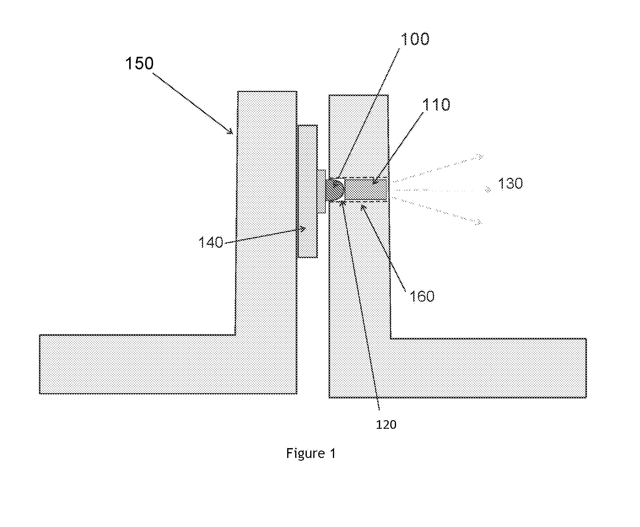
[0039]A design of the Ti-Sapphire based light source, as shown in FIG. 1, includes an excitation light source consisting of high power (0.2-1.0 Watt) blue or blue-green LED 100 with a center wavelength between 560 to 490 nm, with a molded-in plastic lens positioned against Ti+3 doped sapphire laser rod 110, with small air space 120 between the LED lens and the Ti-Sapphire rod due to curvature of the lens. Optionally, the air space between the LED lens and the Ti-Sapphire rod may be filled with a clear optical encapsulant such as an optical epoxy or optical grade silicone e...


PUM


Abstract

A light source for near-infrared transmission and reflection spectroscopy can be constructed from a combination of a high power blue or blue-green light emitting diode (LED) and a phosphor element based on an inorganic material. The phosphor element absorbs the LED light and, in response to the LED excitation, emits luminescence that continuously covers the 700-1050 nm range. One possible material that can be used for such a near-infrared emitting phosphor element is a single crystal rod of Ti+3 doped Sapphire. An alternative near-infrared emitting phosphor material is a disk or rectangular shaped composite of Ti+3 doped Sapphire powder embedded in a clear optical epoxy or silicone encapsulant. Such a combination of a blue LED for excitation of a phosphor element that emits in a broad wavelength band has been widely used in white LEDs where the emission is in the 400-700 nm range.

Description

CROSS-REFERENCE TO RELATED APPLICATIONS[0001]This utility patent application claims priority from U.S. provisional patent application Ser. No. 62 / 056,941, filed Sep. 29, 2014, titled “Solid State Broad Band Near-Infrared Light Source” naming inventor Ronald H. Micheels. The disclosures herein can be used in various applications, including the systems described in U.S. Pat. Pub. No. 2013 / 0265568, “OPTICAL ANALYZER FOR IDENTIFICATION OF MATERIALS USING TRANSMISSION SPECTROSCOPY”, published Oct. 10, 2013, naming inventors Ronald H. Micheels and Don J. Lee, and U.S. Pat. No. 8,859,969, “OPTICAL ANALYZER FOR IDENTIFICATION OF MATERIALS USING REFLECTANCE SPECTROSCOPY”, issued Oct. 14, 2014, naming inventors Ronald H. Micheels and Don J. Lee, both of which are hereby fully incorporated by reference.COPYRIGHT NOTICE[0002]A portion of the disclosure of this patent document contains material that is subject to copyright protection. The copyright owner has no objection to the facsimile reprodu...

Claims


Application Information

Patent Timeline
Patent Type & Authority Applications(United States)
IPC IPC(8): G01J3/10F21K99/00F21V7/04F21V7/22F21V9/16
CPCG01J3/108F21V7/043F21K9/56F21Y2101/02F21V7/22F21V2200/10F21V9/16G01J3/024G01J3/0216G01N21/359G01N21/255
Inventor MICHEELS, RONALD, H.
Owner INNOVATIVE SCI TOOLS
Why Eureka
Try Eureka