Systems and Methods for Affixing A Prosthetic to Tissue

Active Publication Date: 2016-04-07
MICRO INTERVENTIONAL DEVICES
View PDF3 Cites 40 Cited by
  • Summary
  • Abstract
  • Description
  • Claims
  • Application Information

AI Technical Summary

Benefits of technology

[0017]Where radial pressure has proven a viable means of securement for aortic valve prosthesis, anchors will serve as the most efficient method of securement in mitral valve replacement. The design of the anchor addresses various problems associated with anchoring or suturing a prosthesis within the heart. First, the tension component serves a dual purpose in the anchor's design: it pulls the anchor head component in a distal direction after deployment, allowing the barbs to set more securely, and also allows for the prosthesis to remain in more constant contact with the tissues of the heart, despite their fluctuating throughout the cardiac cycle. This means that where other anchoring technologies, or suturing methods, require tensioning in order to most effectively secure a prosthesis to the implant site, the anchor tensions itself. This allows for a procedure to be completed on a level of significantly less invasiveness to the patient, encouraging faster re

Problems solved by technology

For example, percutaneous repair involves modified surgical techniques, which can limit the benefits of the procedure.
Annular rings may lack effectiveness, and include risks of erosion, perforation, and coronary artery thrombosis.
Edge-to-edge repair can be technically demanding, and may lack long term durability.
Depending upon the particular valve failure, combinations of different repair techniques may be necessary, further complicating the procedure and limiting its effectiveness.
Open surgery solutions for heart valve replacement, however, carry significant risks to the patient.
Moreover, fixing the heart valve implant to the implant site may be challenging, as the implant site may form an irregular shape, may lack calcium to secure the valve, or may cause difficulty in fixing the implant valve with the proper orientation.
Further, although long-standing surgical methods for the implantation and the design of aortic valve prosthesis have proven both safe and reliable over the past few decades, it has been well documented that the transition of these same prosthetic designs and surgical methods, to mitral valve replacement, has fallen far short both in terms of safety and reliability.
But, the mitral valve lacks the necessary rigidity and consistency of size that allow radial p

Method used


Image

  • Systems and Methods for Affixing A Prosthetic to Tissue
  • Systems and Methods for Affixing A Prosthetic to Tissue
  • Systems and Methods for Affixing A Prosthetic to Tissue

Examples


Embodiment Construction

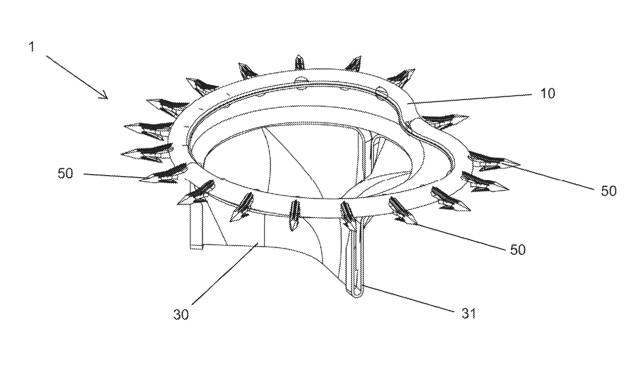
[0103]As set forth in greater detail below, example embodiments of the present invention allow for the effective and reliable deployment of specially designed TCAT anchors, by means of a proprietary catheter-based delivery mechanism, for the purposes of securing a prosthesis to the tissues of the human heart.

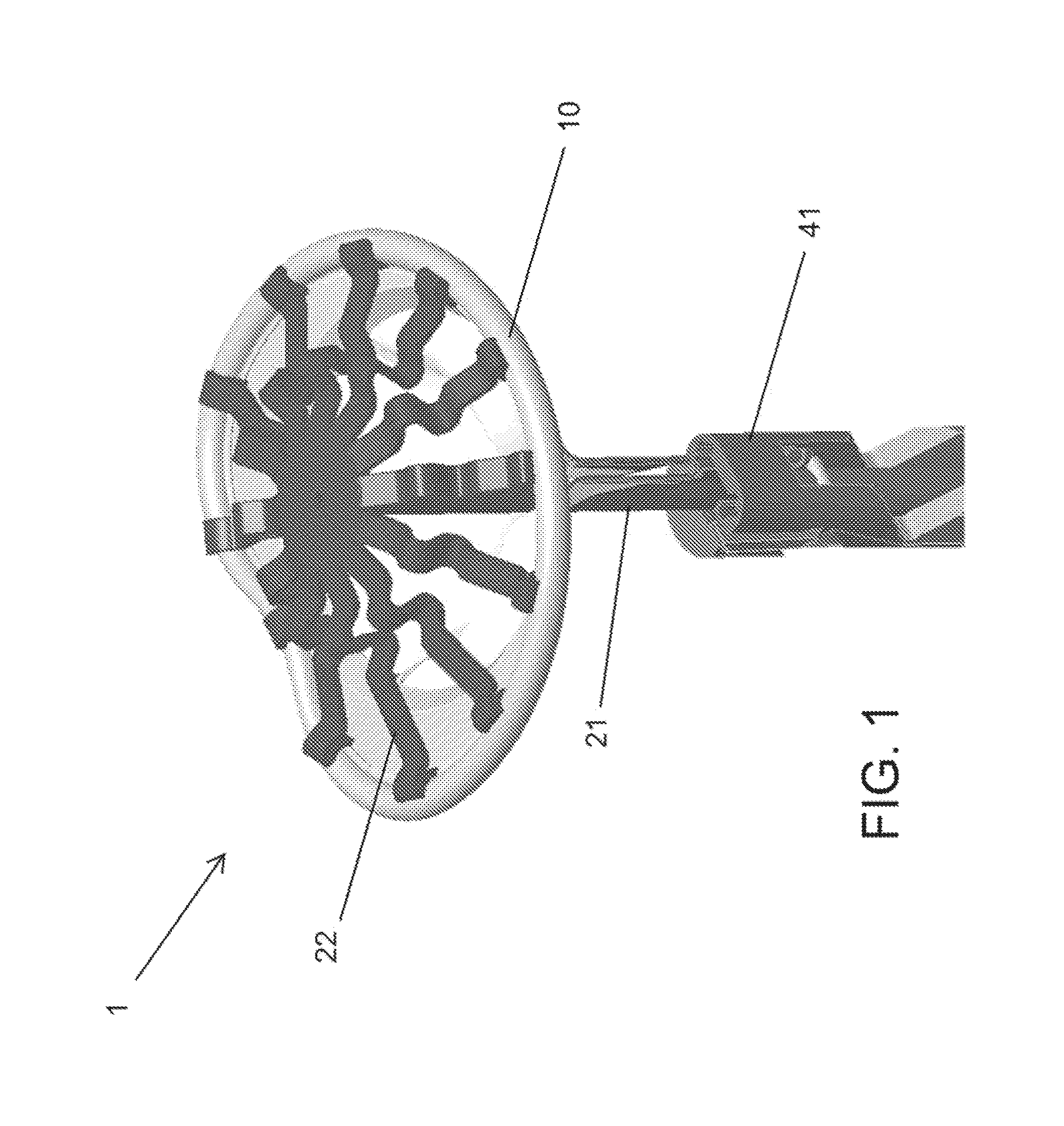
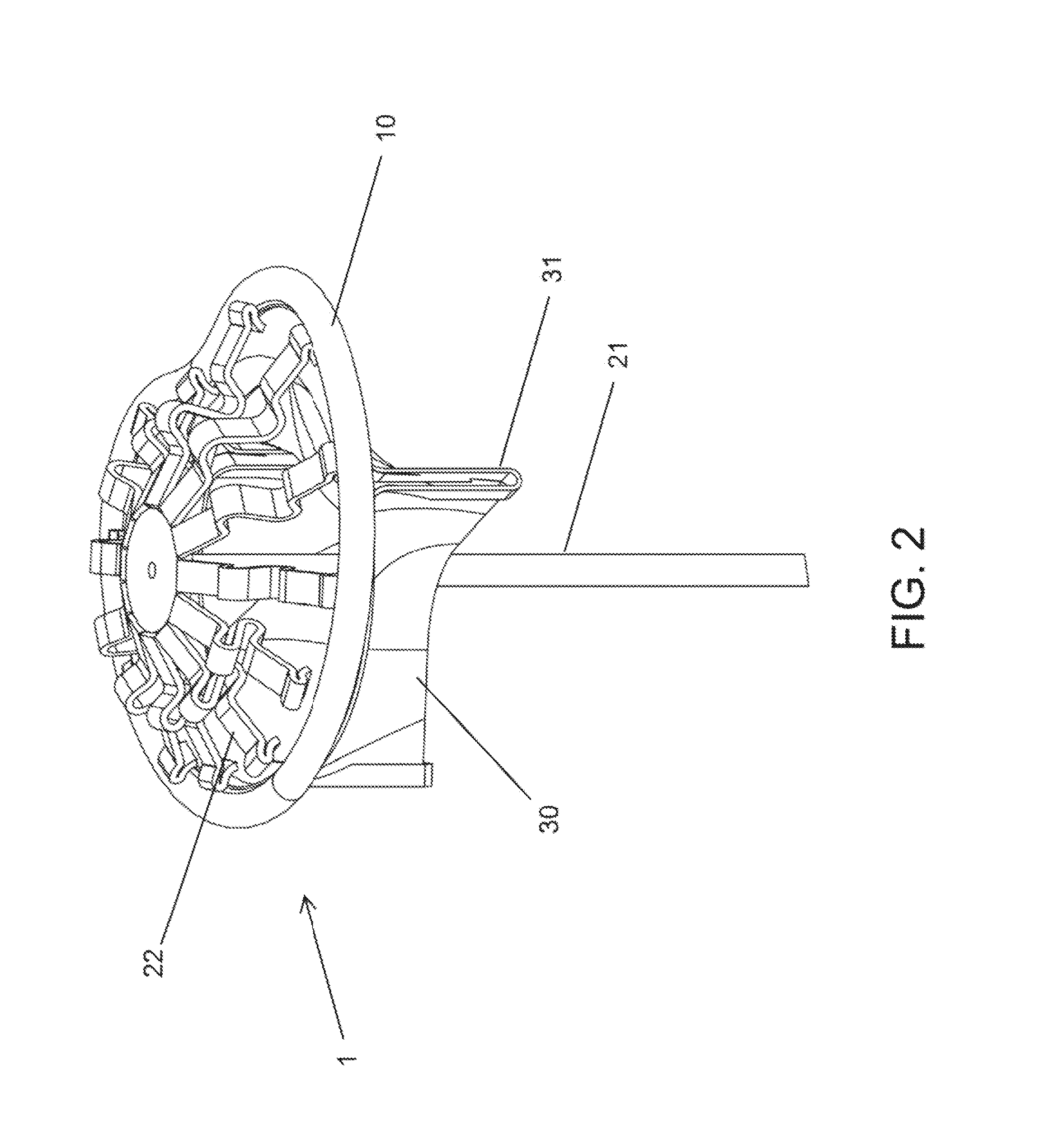
[0104]FIG. 1 illustrates heart valve replacement prosthesis 1 having ring 10, which, in an exemplary embodiment, may be elastic. FIG. 1 further illustrates applicator 20 having applicator shaft 21 and spring arms 22. Spring arms 22 may be affixed to the distal end of the applicator shaft 21, and may connect the distal end of the applicator shaft 21 to the ring 10 of the replacement prosthesis 1. FIG. 1 further illustrates driver 40, as will be described in more detail below.

[0105]As will be generally understood, as described by, for example, U.S. Pat. No. 7,621,948, the entirety of which is hereby incorporated by reference as if fully disclosed herein, the replacement prosthesis...


PUM


Abstract

Systems and methods recited herein provide for affixation of a prosthetic valve to surrounding tissue, by at least one anchor and an anchor deployment device. The prosthetic valve device may be compliant with native tissue and may receive the at least one anchor in at least one anchor receptacle to affix the prosthetic valve to native tissue. The anchor may include a distal tip, a proximal head, and a tension component, such that upon deployment into tissue the tension component is situated in a tensioned state to exert a pulling force on the distal end of the anchor.

Description

CROSS-REFERENCE TO RELATED APPLICATIONS[0001]This application claims the benefit of the filing date of, and incorporates by reference thereto in its entirety, U.S. Provisional Patent Application Ser. No. 62 / 088,680, filed on Dec. 7, 2014.[0002]This application is also a continuation-in-part of, claims the benefit of the filing date of, and incorporates by reference thereto in its entirety, U.S. patent application Ser. No. 14 / 737,408, filed Jun. 11, 2015, which claims the benefit of the filing date of U.S. Provisional Patent Application Ser. No. 62 / 010,680, filed on Jun. 11, 2014, and which is also incorporated by reference herein in its entirety.[0003]Further, each of the following is hereby incorporated by reference thereto in its entirety: U.S. patent application Ser. No. 14 / 321,476, filed Jul. 1, 2014, U.S. patent application Ser. No. 14 / 301,106, filed Jun. 10, 2014, U.S. patent application Ser. No. 13 / 843,930, filed Mar. 15, 2013, PCT Application No. PCT / US14 / 30868, filed Mar. 1...

Claims


Application Information

Patent Timeline
IPC IPC(8): A61F2/24
CPCA61F2/2436A61F2/2418A61F2/2409A61B17/068A61B2017/0647A61F2/2427
Inventor WHITMAN, MICHAEL P.
Owner MICRO INTERVENTIONAL DEVICES
Why Eureka
Try Eureka