Cathode Material for Lithium-Ion Rechargeable Batteries

Active Publication Date: 2016-04-07
UMICORE AG & CO KG
View PDF1 Cites 38 Cited by
  • Summary
  • Abstract
  • Description
  • Claims
  • Application Information

AI Technical Summary

Benefits of technology

[0034]Viewed from a first aspect, the invention can provide a lithium metal oxide powder for use as a cathode material in a rechargeable battery, consisting of a core and a surface layer, the lithium metal oxide having the general formula Lix(CoaMbAc)2−xO2±δ, with x≦0.995, b>0, c≧0, a+b+c=1, |δ|≦0.1 (|δ|=absolute value of δ), M=(MnmNin) with m+n=1, A is a dopant, wherein the surface layer comprises either one or both of a cubic phase oxide having a crystal structure with a Fm-3m space group, and a cubic phase oxide having a crystal structure with a Fd-3 mS space group. In the formula, n may be greater than or equal to m. Also, at the surface of the powder the molar ratio Ni:Mn may be >1, said surface Ni:Mn molar ratio being greater than the molar ratio n/m. In different embodiments, either x≧0.970 or 0.974≦x≦0.993. In an embodiment, 0<c≦0.03, and A is either one or more dopants selected from the group consisting of Mg, Ti, Al and Zr. In another embodiment, the cubic phase oxide having a crystal structure with a Fm-3m space group has a lattice constant a w

Problems solved by technology

Despite of some inherent limitations like poor safety and high cost LiCoO2 still is the most applied cathode material for rechargeable lithium batteries.
Problems which appear or become more severe if the charging voltage is increased are (a) low safety, (b) poor storage properties during storage of charged batteries at elevated temperature and (c) poor cycling stability.
Partial improvements have been achieved but the basic problems have not been fully resolved.
One basic limitation originates from the surface area dilemma.
However, a high surface area increases the area where unwanted side reactions between electrolyte and charged cathode take place.
These side reactions are the course of poor safety, poor cycling stability at elevated voltage and of poor storage properties of charged cathode at elevated temperature.
Furthermore, high surface area materials tend to have a low packing density which reduces the volumetric energy density.
Another basic limitation originates from the cobalt stoichiometry.
Lithium-nickel

Method used


Image

  • Cathode Material for Lithium-Ion Rechargeable Batteries
  • Cathode Material for Lithium-Ion Rechargeable Batteries
  • Cathode Material for Lithium-Ion Rechargeable Batteries

Examples


example 1

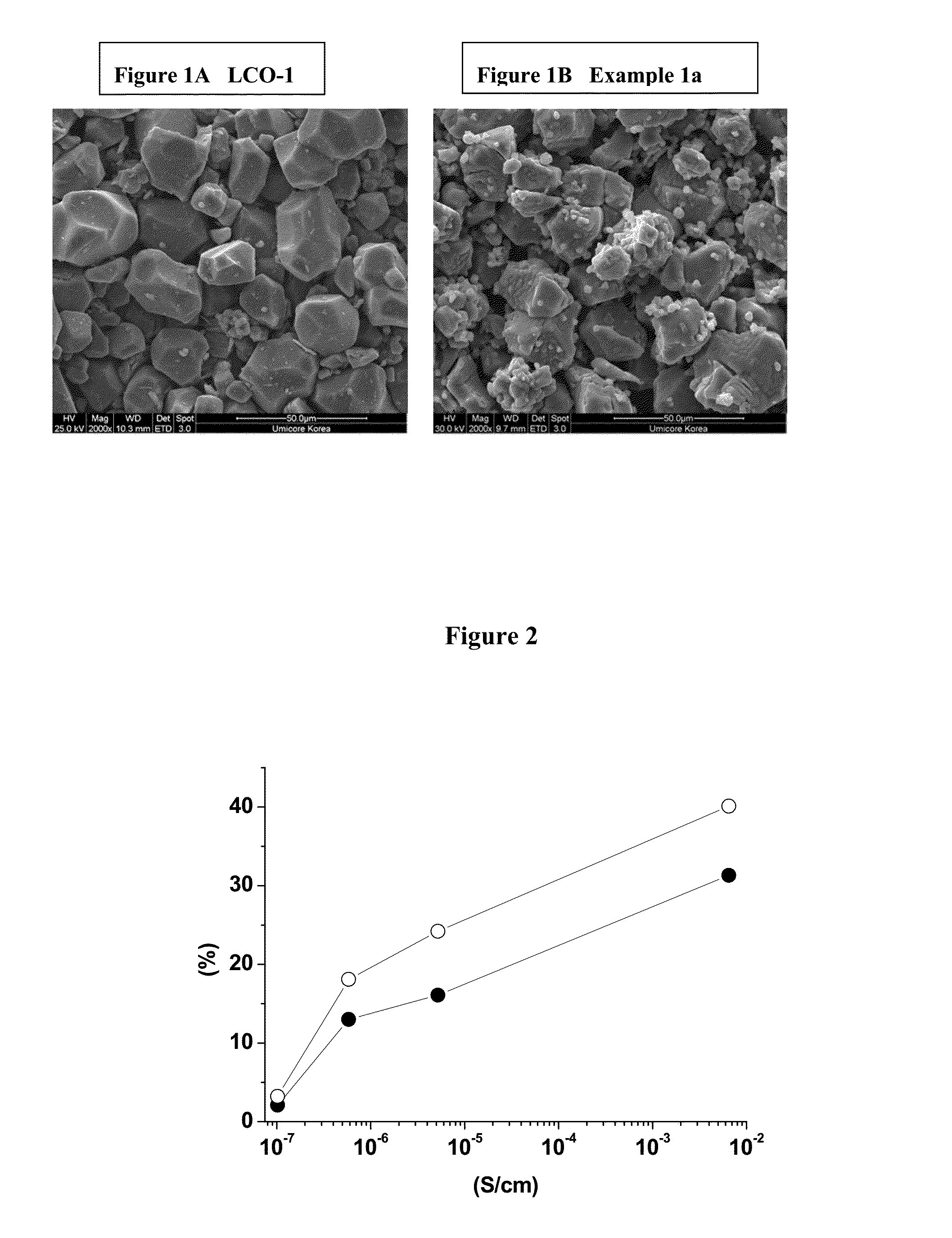
[0079]This example demonstrates that cycle stability improves as electrical conductivity decreases. The improved stability and decrease of conductivity is achieved by optimizing the Li:metal ratio.

[0080]Preparation of LCO-1: 0.25 mol % titanium and 0.5 mol % magnesium doped Co(OH)2 is prepared in a pilot line, as precursor for LiCoO2. Titanium and magnesium doped LiCoO2 (noted LCO-1) is obtained by means of a standard high temperature solid state synthesis by mixing the precursor with Li2CO3 to achieve an average particle size of 25 μm.

[0081]Preparation of island-coated LCO-1: A cathode powder material is prepared by mixing 95 wt. % of titanium and magnesium doped LiCoO2 (LCO-1), with 5 wt. % of MOOH mixed transition metal oxy-hydroxide with M=Ni0.55Mn0.30Co0.15 and either none or pre-determined amounts of Li2CO3. Examples 1a, 1b and 1c are prepared according to Table 1 and sufficiently mixed to prepare a homogeneous raw material mixture. The mixture is placed in an alumina crucible...

example 2

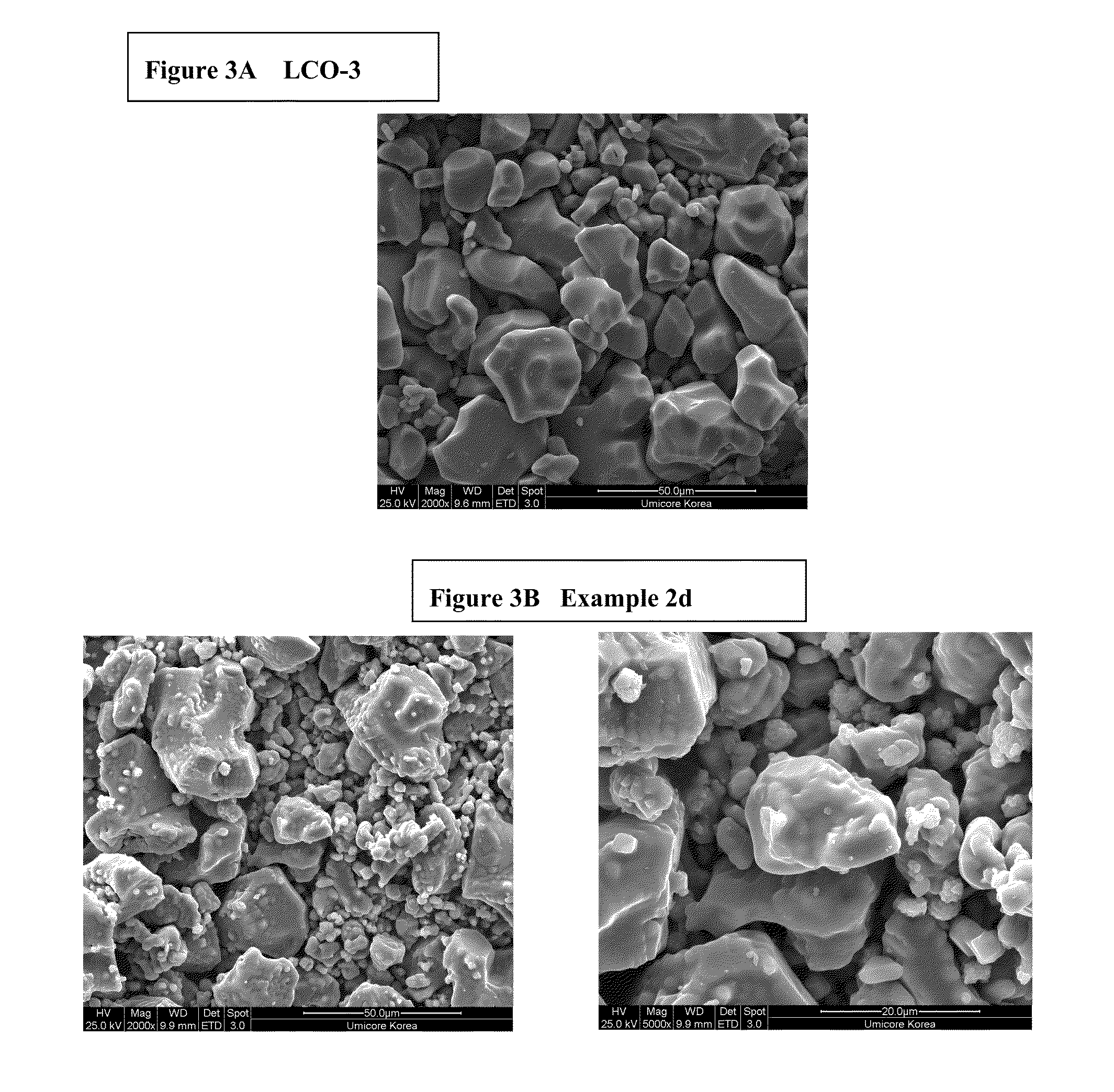
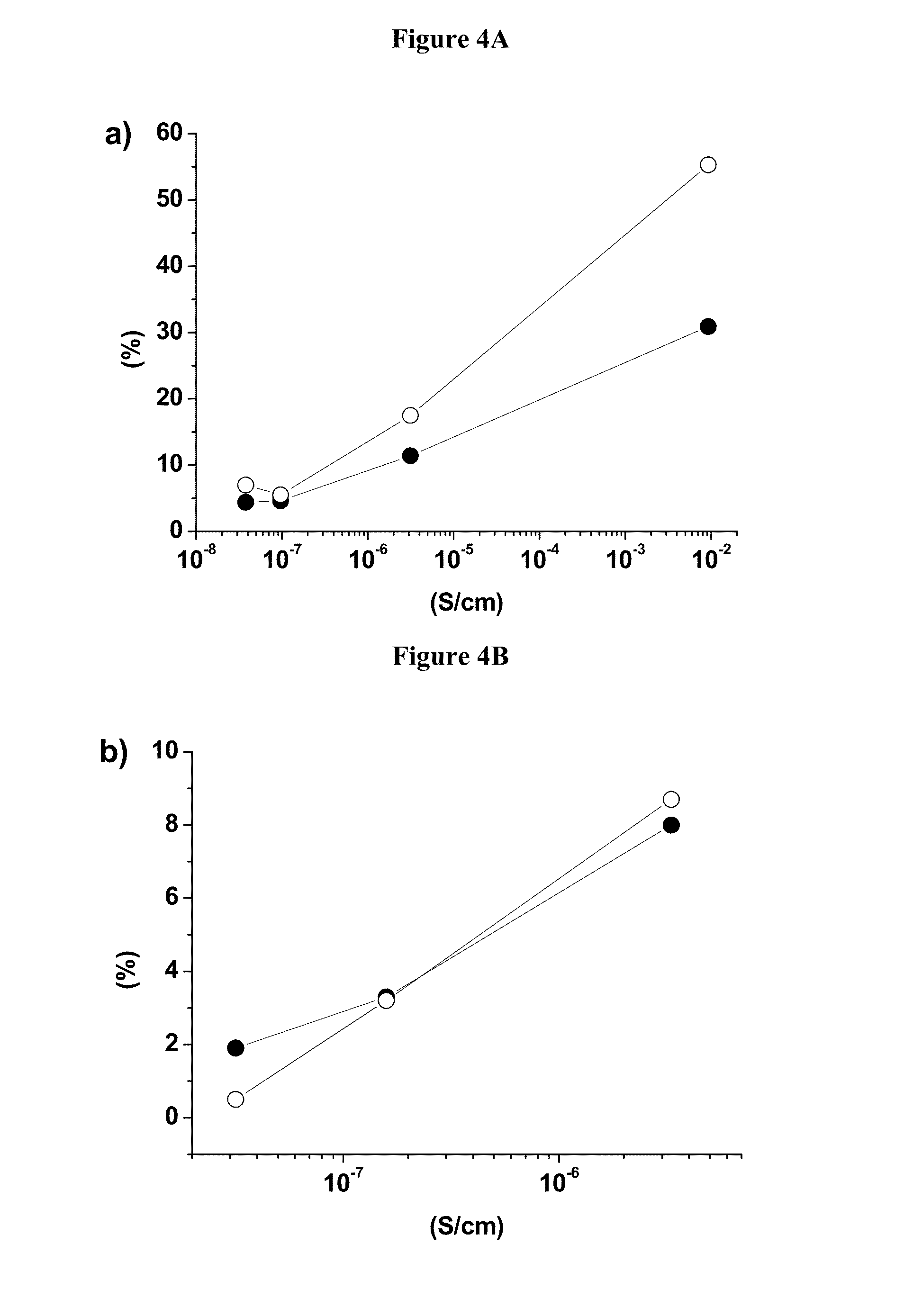
[0092]This example will demonstrate that the cycling stability of island coated LiCoO2 is much higher than that of uncoated LiCoO2, where at the same time its electrical conductivity is about five orders of magnitude lower. The example also provides clear evidence that the cycling stability of the island coated LiCoO2 increases with the decrease of the intrinsic electrical conductivity.

[0093]Preparation of LCO-2: 1 mol % magnesium doped Co(OH)2 as precursor for LiCoO2 is prepared in a pilot line. Magnesium doped LiCoO2 (noted LCO-2) is obtained by means of a standard high temperature solid state synthesis by mixing the precursor with Li2CO3 to achieve an average particle size of 25 μm.

[0094]Preparation of LCO-3: 1 mol % magnesium doped cobalt tetroxide (Co3O4) powder as precursor for LiCoO2 is used (commercially available product from Umicore, Korea). Magnesium doped LiCoO2 (noted LCO-3) is obtained by means of a standard high temperature solid state synthesis by mixing the precurso...

example 3

[0098]This example demonstrates that island coated LiCoO2 having an electronic insulating behavior has superior cycling stability in full cells.

[0099]Preparation of Example 3 (Ex3): Ex3 is prepared on a pilot production line by sintering a mixture of LCO-3 and MOOH (M=Ni0.55Mn0.30Co0.15) in a 95:5 molar ratio and appropriate lithium carbonate addition to achieve a conductivity of less than 5*10−8 S / cm. The average particle size of Ex3 is 25 μm. In this case, the electrical conductivity under an applied pressure of 63 MPa is measured to be 3.94*10−8 S / cm. Coin cell performances at 4.5V and 4.6V of Ex3 are listed in Table 5a and show outstanding electrochemical performances.

TABLE 5aElectrical conductivity and electrochemicalperformances at 4.5 V and 4.6 V of Example 3.DischargeDischargeRatecapacitycapacityperfor-CapacityEnergyElectr.0.1 C1 Cmancefadingfadingconductivity(mAh / g)(mAh / g)3 C (%)1 C (%)1 C (%)(S · cm−1)Example 3187.3183.494.911.470.873.94*10−8at 4.5 VExample 3218.3214.620.2...


PUM


Abstract

Disclosed are a cathode active material and a method to produce the same at low cost. The cathode powder comprises modified doped LiCoO2 carrying a secondary phase having either one of space groups Fm-3m or Fd-3 mS. The modified LiCoO2 is Ni and Mn bearing and has regions of low and high manganese content, where regions with high manganese content are located in islands on the surface. The cathode material has high cycling stability, a very high rate performance and good high temperature storage properties.

Description

[0001]This application is a continuation-in-part of U.S. patent application Ser. No. 13 / 308,704, filed Dec. 1, 2011, which is a continuation-in-part of U.S. patent application Ser. No. 12 / 374,532, filed Jan. 21, 2009, which is a national stage application of PCT / EP2008 / 000313, filed Jan. 17, 2008, which claims the benefit of U.S. Provisional Application No. 60 / 897,823, filed Jan. 29, 2007, European Patent Application No. 07012789.9, filed Jun. 29, 2007, and U.S. Provisional Application No. 60 / 929,613, filed Jul. 5, 2007, the entire contents of each of which is hereby incorporated by reference. U.S. patent application Ser. No. 13 / 308,704 is also a continuation-in-part of PCT / EP2011 / 060681, filed Jun. 27, 2011, which claims priority to U.S. Provisional Application No. 61 / 359,484, filed Jun. 29, 2010, the entire contents of each of which is hereby incorporated by reference.BACKGROUND OF THE INVENTION[0002]The present invention relates to a powderous lithium transition metal oxide, cont...

Claims


Application Information

Patent Timeline
IPC IPC(8): H01M4/485H01M10/0525H01M4/36
CPCH01M4/485H01M10/0525H01M4/366C01G53/50C01P2002/32C01P2002/50C01P2002/72C01P2002/76C01P2002/77C01P2002/85C01P2004/03C01P2004/50C01P2004/51C01P2004/52C01P2004/53C01P2004/61C01P2006/40H01B1/08H01M4/505H01M4/525Y02E60/10Y10T428/2982
Inventor PAULSEN, JENS MARTINBLANGERO, MAXIME
Owner UMICORE AG & CO KG
Why Eureka
Try Eureka