Acoustic apparatus and operation

a technology of acoustic equipment and acoustic power, applied in the direction of sound producing devices, animal husbandry, weapons, etc., can solve the problems of large system size, inability to consider risk-free options, and inability to be mounted and powered by vehicles, and achieve high selectivity.

Active Publication Date: 2016-04-14
CERBERUS BLACK
View PDF10 Cites 7 Cited by
  • Summary
  • Abstract
  • Description
  • Claims
  • Application Information

AI Technical Summary

Benefits of technology

[0033]The device is given the trade name Acoustic-Warning Signal Projector™ or A-WaSP™. Due to its extremely high levels of selectivity; and ability to operate effectively as a projected warning whilst remaining with

Problems solved by technology

Such AHDs could be said to address this capability gap—by enabling a projected warning—however in practice these technologies present a significant safety hazard and so cannot be considered a risk free option.
These technologies are effective at communicating or signalling over a long range, and are very much more compact, mobile and practical than conventional public address systems but they do have some significant drawbacks.
For instance, such systems are typically quite large and must be vehicle mounted and powered.
However the primary drawback for use in Conflict Management is that they are not very directional at the audio frequencies used for verbal communication—which combined with their very high output levels—makes them extremely hazardous at close range to target, bystanders and users.
This means that anyone experiencing the sound source at close range has the potential to suffer instantaneous permanent hearing damage.
This necessitates the user wearing ear protection, preventing normal communication, and puts bystanders—even those behind the device—at serious risk of harm in a very short timeframe.
A further problem is that there is no means to control or record the dosage experienced by the target.
This means that there is no way of proving that the sound levels experienced by the target or anybody else are within safe limits.
This potentially opens up the users of such devices to litigation for exposing targets, operators and bystander

Method used


Image

  • Acoustic apparatus and operation
  • Acoustic apparatus and operation
  • Acoustic apparatus and operation

Examples


Embodiment Construction

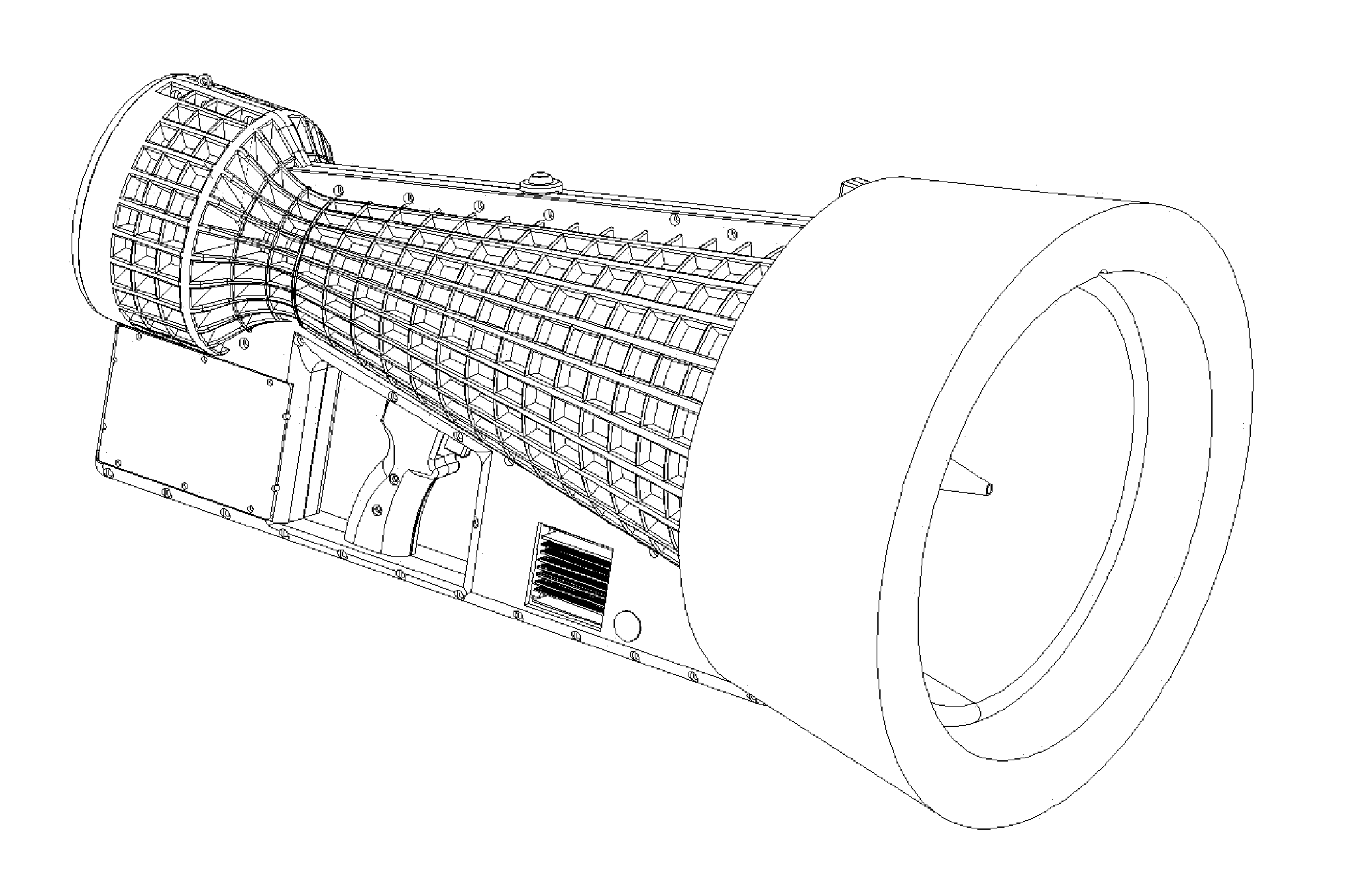
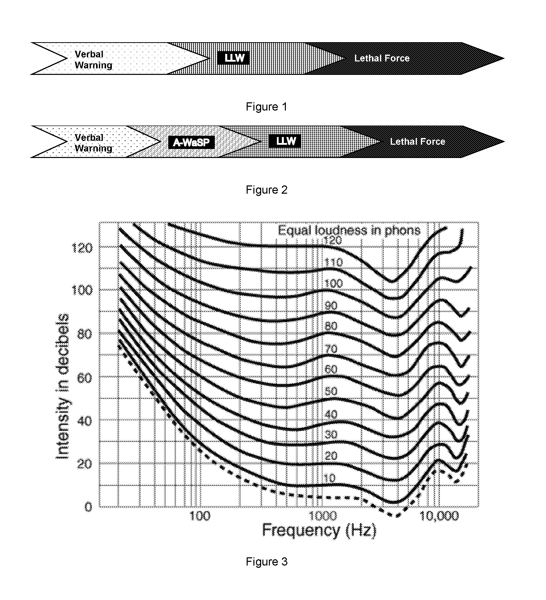
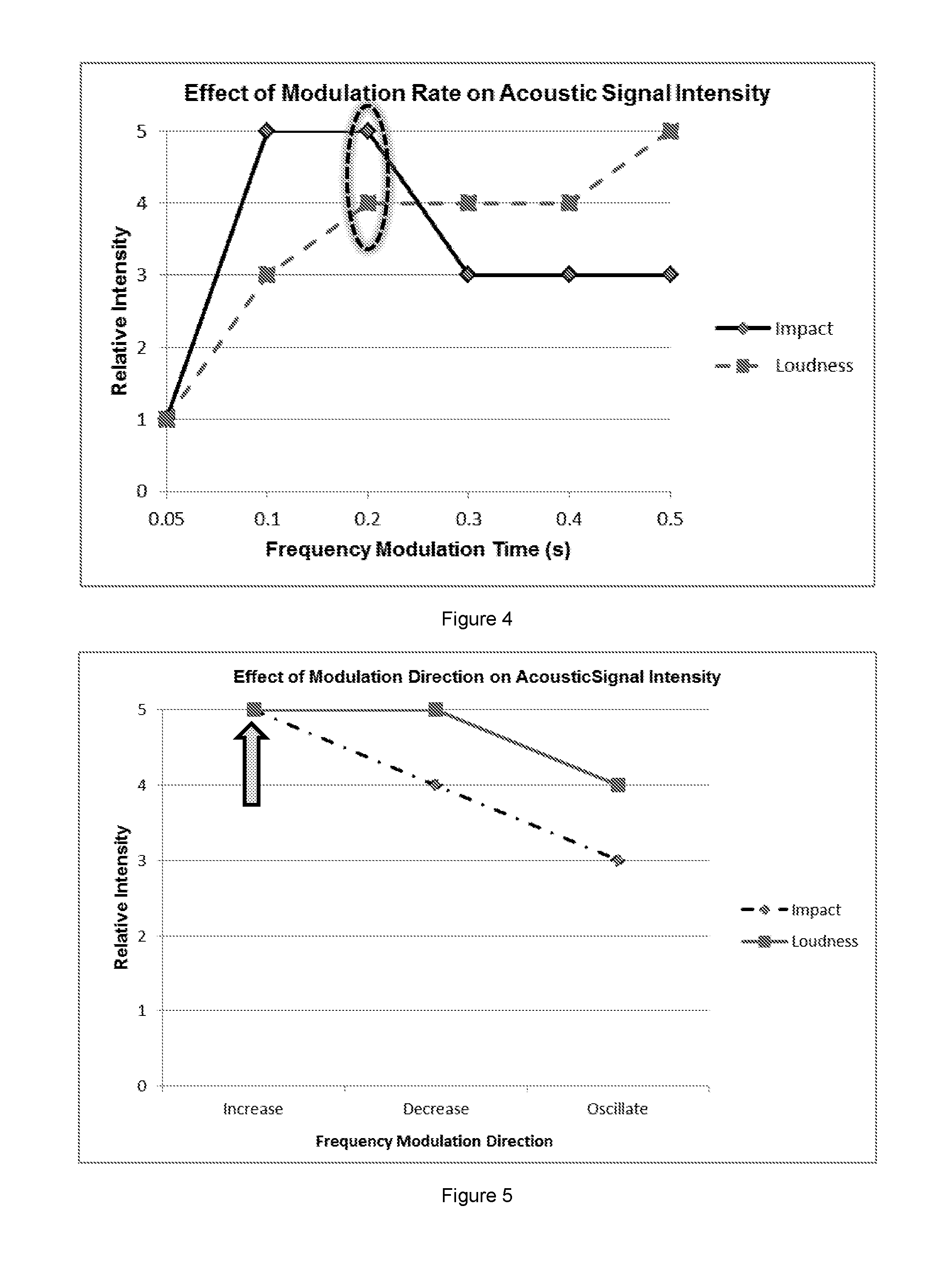
[0063]In overview a design for a portable acoustic device is presented that projects a specific acoustic waveform towards a target, creating a narrow beam of sound that is highly selective, minimising exposure to users and bystanders, whilst enabling a controlled dosage of sound to be applied to the target. This narrow cone of sound acts as a clear warning of Police attention at range and as the target nears the intensity rises creating a naturally escalating deterrent. The acoustic waveform is specified using principals from the field of psycho-acoustics combined with empirical human studies. The design of the device is tailored to this waveform which allows a very high degree of directivity to be achieved. It is not intended as a tool for the communication of verbal messages. This waveform achieves maximum impact and intensity at the target whilst using a relatively low sound pressure level. This means that the exposure levels can be controlled to ensure they are within existing h...


PUM


Abstract

A portable acoustic warning device which projects a specific acoustic waveform towards a target, creating a narrow beam of sound that is highly selective, minimising exposure to users and bystanders, whilst enabling a controlled dosage of sound to be applied to the target. The design of the device is tailored to this waveform thus achieving a very high degree of directivity. It is not intended for communicating verbal messages. This waveform achieves maximum intensity at the target whilst using a relatively low sound pressure level; meaning that the exposure levels can be controlled to ensure they are within existing health and safety legislation. A laser range finder limits the sound level at the target to a pre-determined level. An integrated camera is used to aid aiming. Video footage is recorded with use; along with the sound level at the target, exposure duration, time, date and GPS coordinates.

Description

BACKGROUNDTechnical Field of the Invention[0001]Conflict Management is a core function of Police and Law Enforcement agencies across the world. It is also increasingly a function of military forces engaged in peace-keeping and nation-building. The underlying philosophy of Conflict Management is to enable the Police to minimise, as far as possible, the risk of harm to all individuals who find themselves in a conflict situation by managing that situation carefully. Over the years a variety of technologies have been developed to deal with conflict situations and provide new tools to Law Enforcement to help manage them more effectively. These technologies include such things as batons, tear gas, irritant sprays, water cannon, electro-shock devices and baton rounds (rubber bullets). All these technologies have been developed to bridge the gap between passive warnings and the need to use lethal force. Such technologies are categorised as Less Lethal Weapons (LLWs).[0002]The availability o...

Claims


Application Information

Patent Timeline
IPC IPC(8): H04R1/34H04R3/00F41H13/00H04R1/30
CPCH04R1/345H04R1/30H04R2430/01F41H13/0081H04R2201/34H04R3/00G10K11/26G10K13/00A01M29/16G10K15/04H04R1/20
Inventor HENRY, MATTHEWKINSELLA, EDWARD
Owner CERBERUS BLACK
Why Eureka
Try Eureka