
Damper-integrated blower having improved airtightness

a blower and integrated technology, applied in the field of blowers with integrated dampers, can solve the problems of large amount of fan motor power consumption, difficult to apply dampers to compact and slim type heat recovery ventilators, and high installation costs, so as to reduce wind pressure and noise generation, improve air tightness, and reduce the effect of noise generation

Active Publication Date: 2016-04-28
CENDORI
View PDF0 Cites 7 Cited by
  • Summary
  • Abstract
  • Description
  • Claims
  • Application Information

AI Technical Summary

Benefits of technology

The present invention is a compact and simple blower that has improved airtightness and reduced noise and wind pressure. The invention has a single plate vane module mounted integrally with the exhaust port, unlike conventional practice where multiple vanes are operated cooperatively. The blower has only one damper motor mounted on the exterior, making it efficient in heat recovery ventilators for windows or window frames with small installation spaces. It can also be used for all kinds of blowers that move fresh outdoor air into indoor air while keeping the heat energy of the indoor air. The invention reduces the number of parts, saving manufacturing costs.

Problems solved by technology

Among them, the duct type ceiling mounted heat recovery ventilators cause large amount of fan motor power consumption due to the generation of static pressure from the duct and need a relatively high installation cost.
When the heat recovery ventilator does not operate, by the way, a damper is generally mounted on the supply and exhaust grills to block the indoor and outdoor air, and in this case, it is actually hard to apply the damper to the compact and slim type heat recovery ventilators.

Method used


Image

  • Damper-integrated blower having improved airtightness
  • Damper-integrated blower having improved airtightness
  • Damper-integrated blower having improved airtightness

Examples


Embodiment Construction

[0021]Hereinafter, an explanation on a damper-integrated blower having improved airtightness according to the present invention will be in detail given with reference to the attached drawing.

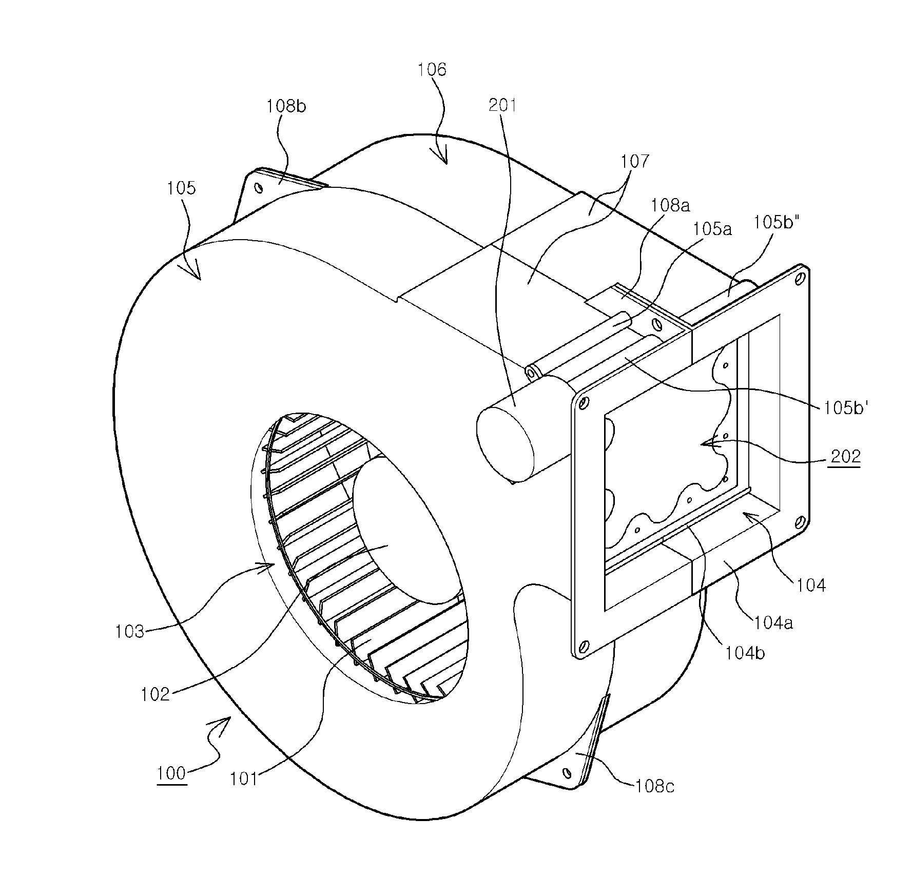
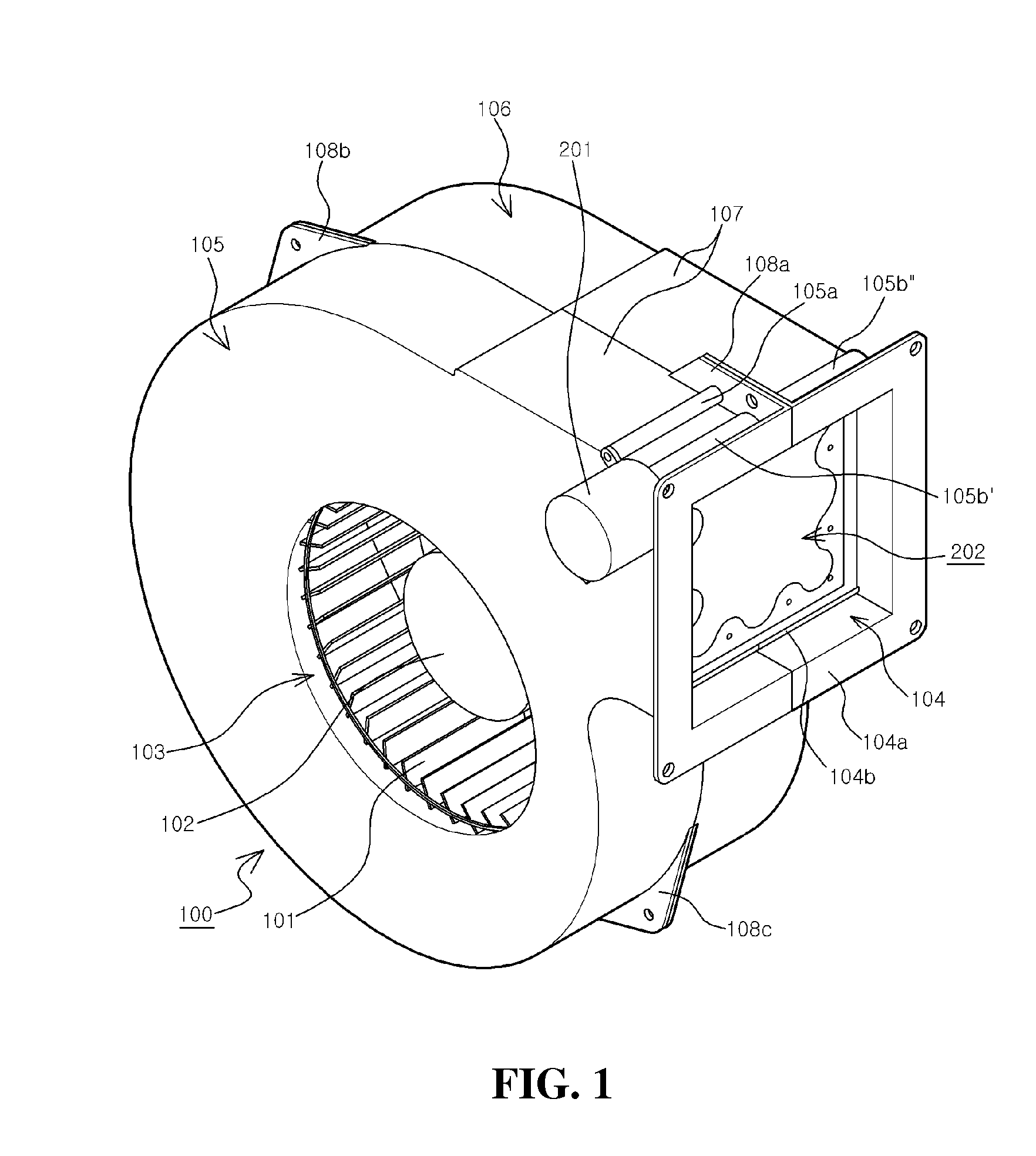
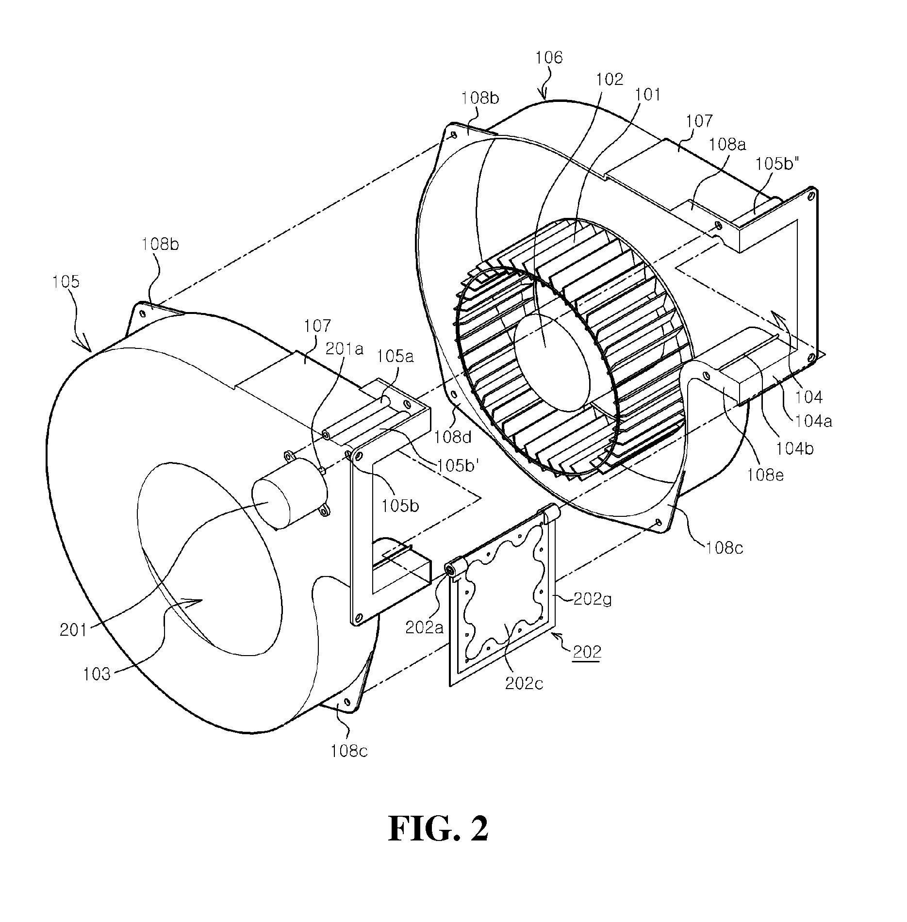
[0022]FIG. 1 is a perspective view showing the assembled state of a damper-integrated blower having improved airtightness according to the present invention, FIG. 2 is an exploded perspective view showing the assembled state of the main parts of the damper-integrated blower according to the present invention, FIG. 3 is an exploded perspective view showing partially cut-off main parts of the damper-integrated blower according to the present invention, and FIG. 4 is a separate perspective view showing the assembled state of a vane module as a main part of the damper-integrated blower according to the present invention.

[0023]According to the present invention, a damper-integrated blower 100 includes a blower fan 101 embedded in a shaft center of a suction port 103 formed on the side peripheral surf...


PUM


Abstract

The present invention relates to a damper-integrated blower having improved airtightness, which comprises a blower casing a having a suction port and a blower casing b fastened to the casing a from the opposite side; a vane stopper protrusion is formed on bottom surface of the exhaust port, and a vane contact housing part is formed above the exhaust port; damper motor screw fixing parts integrally protrude from the outer upper surface of the vane contact housing part of the blower casing a; a damper motor shaft hole is bored in a damper motor shaft hole protrusion part which is integrally formed on the outer upper side of the vane contact housing part of the blower casing a; a vane rotation shaft protrudes from the inner surface of a damper motor shaft hole protrusion part of the blower casing b facing the damper motor shaft hole protrusion part; an eccentric damper motor shaft of a damper motor is introduced into the damper motor shaft hole so as to connect with the blower casing a; a vane as a single member is connected to the damper motor shaft and the vane rotation shaft so as to open and close the exhaust port; and a gasket is coupled to the four edges of the vane providing a vane module.

Description

TECHNICAL FIELD[0001]The present invention relates to a damper-integrated blower that is applied to cut off the air introduced into a heat recovery ventilator, and more particularly, to a damper-integrated blower having improved airtightness that is capable of performing a ventilating operation, through which fresh outdoor air is moved into indoor air, while keeping the heat energy of the indoor air.BACKGROUND ART[0002]So as to improve the quality of indoor air, generally, deodorization or dust collection is conducted by means of negative ion air purifiers or electric dust collectors, and recently, heat recovery ventilators, which serve as indoor and outdoor air ventilation systems allowing for the loss of indoor heat energy, have been introduced. The heat recovery ventilators are classified into duct type ceiling mounted ventilators, ductless floor mounted ventilators, and window mounted ventilators.[0003]Among them, the duct type ceiling mounted heat recovery ventilators cause lar...

Claims


Application Information

Patent Timeline
Patent Type & Authority Applications(United States)
IPC IPC(8): F04D25/14F24F7/06F04D29/42
CPCF04D25/14F24F7/065F04D29/4206F24F13/1406F04D29/4226F04D29/464F04D29/646F04D29/626F05D2250/52F04D29/083F04D29/023F04D29/624F16J15/16F24F7/007F24F13/1426F24F13/1413F24F13/15F05D2210/12F05D2240/55F24F13/14F24F13/10
Inventor PARK, MUN SU
Owner CENDORI
Learn More