Charge-discharge device with equalization function using both convertor and multi-stage voltage doubler rectifier circuit

a voltage doubler rectifier and charge-discharge technology, applied in the direction of charging/discharging current/voltage regulation, secondary cell servicing/maintenance, electrochemical generators, etc., can solve the problems of reducing the utilizable energy, accelerating the progression of degradation, and increasing the complexity of the circuit configuration, so as to eliminate the voltage variation among the electricity storage cells, reduce the size and cost of the circuit, and reduce the effect of small electric power

Active Publication Date: 2016-04-28
JAPAN AEROSPACE EXPLORATION AGENCY
View PDF1 Cites 12 Cited by
  • Summary
  • Abstract
  • Description
  • Claims
  • Application Information

AI Technical Summary

Benefits of technology

[0014]In the equalization function-equipped charge-discharge device of the present invention, an equalization function can be newly added by connecting the multi-stage voltage doubler rectifier circuit to a switching node in a charge-discharge device using a conventional converter. In a typical embodiment, charging and discharging of electricity storage cells are mainly performed by the converter, and the multi-stage voltage doubler rectifier circuit is operable to supply only small electric power for eliminating a voltage variation among the electricity storage cells. Thus, a charge-discharge circuit section (converter) and an equalization circuit section (multi-stage voltage doubler rectifier circuit) can be adequately designed separately, so that it bec

Problems solved by technology

The variation occurring in the electricity storage module causes problems such as accelerated progression of degradation, and reduction in utilizable energy.
However, many of the types require a large number of switches, causing a problem of an increase in complexit

Method used


Image

  • Charge-discharge device with equalization function using both convertor and multi-stage voltage doubler rectifier circuit
  • Charge-discharge device with equalization function using both convertor and multi-stage voltage doubler rectifier circuit
  • Charge-discharge device with equalization function using both convertor and multi-stage voltage doubler rectifier circuit

Examples


first embodiment

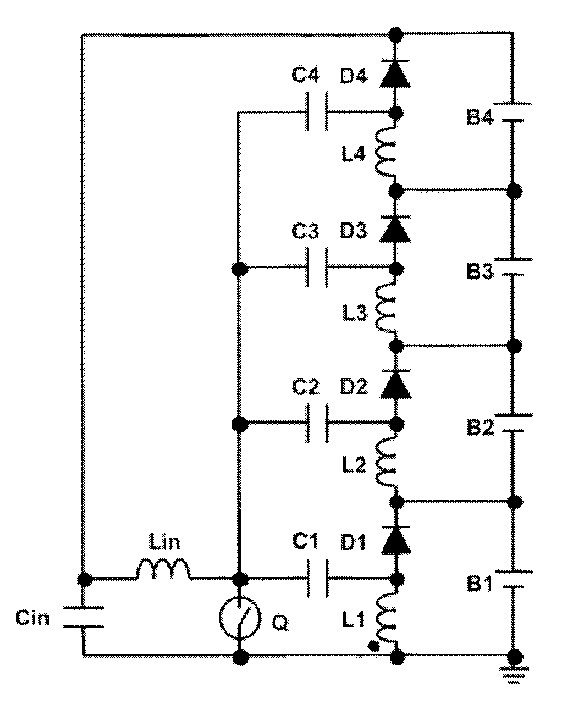
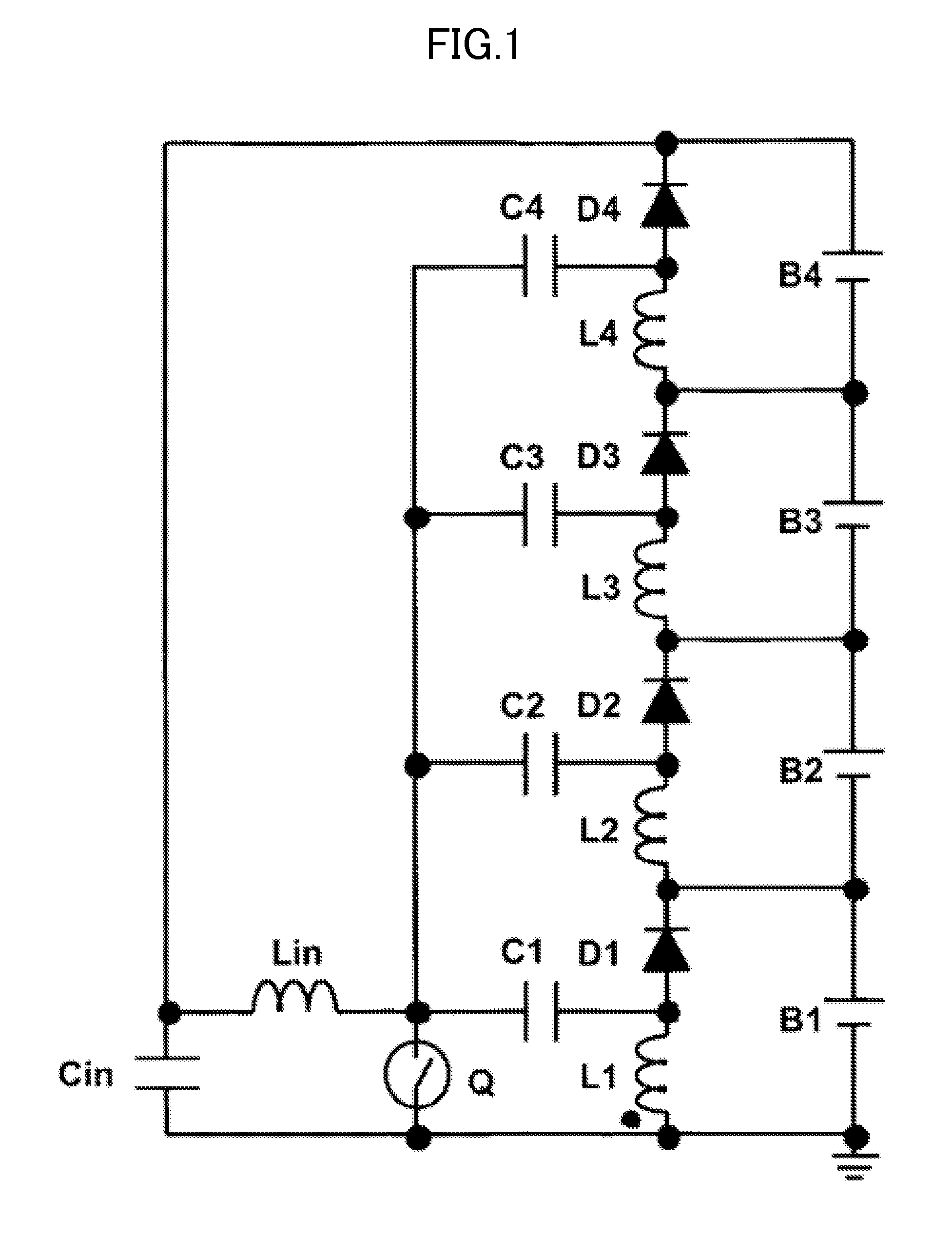
[0070]FIG. 11 illustrates a circuit diagram of a voltage equalization function-equipped charging system in which four series-connected electricity storage cells group B1 to B4 are connected to a charge device according to a first embodiment of the present invention, wherein the charge device comprises the SEPIC converter illustrated in FIG. 4d, and the input circuit and the multi-stage voltage doubler rectifier circuit illustrated in FIG. 7. A switching node composed of a connection point of the capacitor Cet, the diode Do and the inductor L2 in the SEPIC converter is connected to the multi-stage voltage doubler rectifier circuit via the input circuit. An output terminal, i.e., the diode Do, of the SEPIC converter is connected to the capacitors Cout1 to Cout4, and the capacitors Cout1 to Cout4 are connected to the electricity storage cells B1 to B4. Therefore, the electricity storage cells B1 to B4 are serially charged by an output voltage of the SEPIC converter. On the other hand, ...

second embodiment

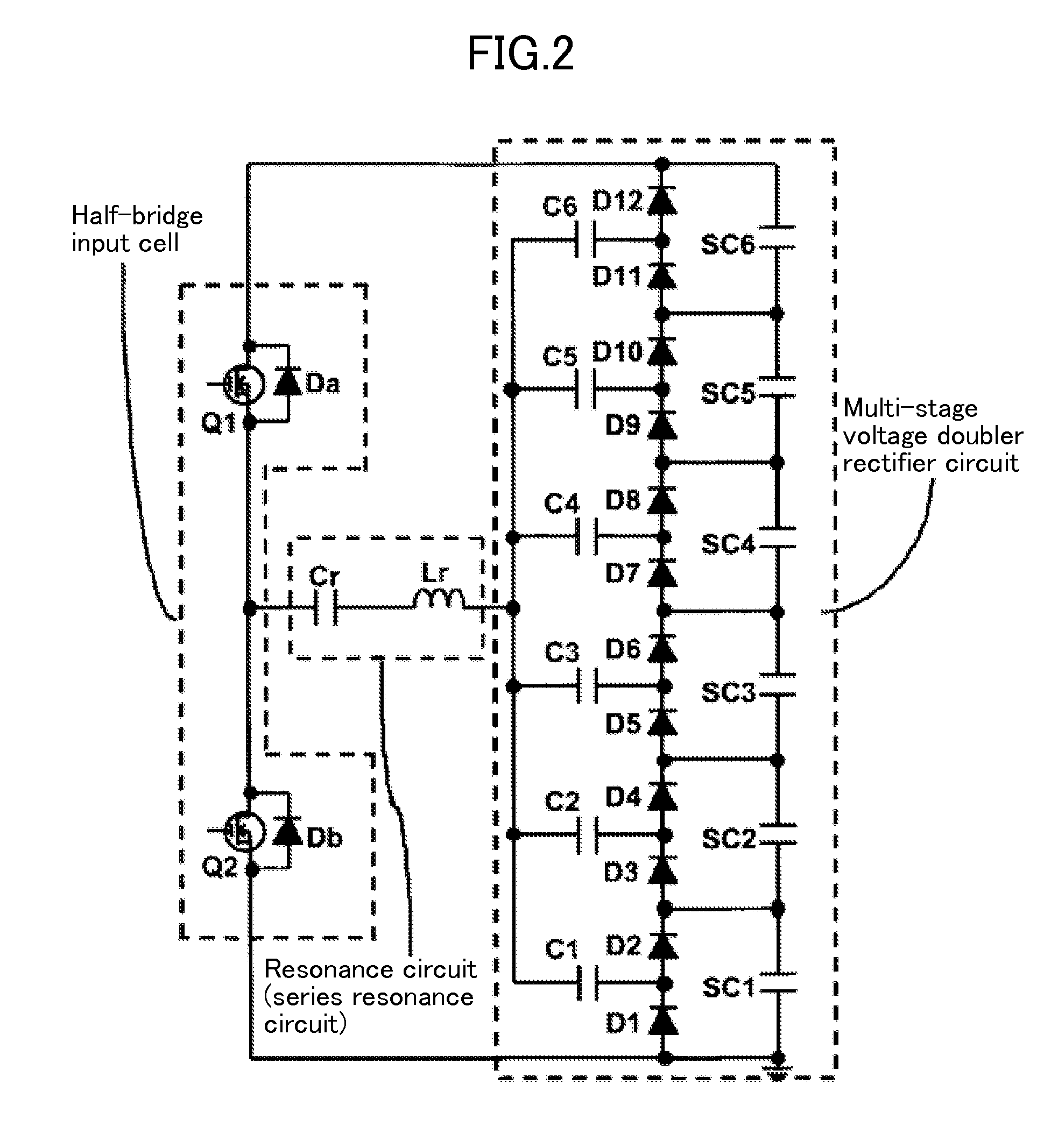
[0077]A resonance circuit may also be used as the input circuit. As one example, FIG. 14 illustrates a circuit diagram of a configuration in which a series resonance circuit is used as the input circuit, and connected to the multi-stage voltage doubler rectifier circuit.

[0078]The series resonance tank is composed of a resonance inductor Lr and a resonance capacitor Cr, and a transformer and the subsequent circuit are the same as those illustrated in FIG. 7. A rectangular waveform voltage VSN generated at a switching node in a converter is applied between terminals A, B, so that a sine wave-shaped AC (alternate current) voltage is input into the multi-stage voltage doubler rectifier circuit.

[0079]FIG. 15 presents operating waveforms generated when the circuit illustrated in FIG. 14 is operated in a DCM (Discontinuous Conduction Mode). iLr represents a current flowing through the resonance inductor Lr (a current flowing in a direction indicated by the arrowed line in FIG. 14 is define...

third embodiment

[0092]The embodiments of the equalization function-equipped charge devices have been described above. The charge devices are constructed using a unidirectional converter configured to transmit electric power in one direction. This charge device of the present invention may be configured using a bidirectional converter so as to allow electric power to be bidirectionally transmitted. By this, an equalization function-equipped charge-discharge device according to the present invention can be obtained. As one example, the charge-discharge device according to the present invention can be obtained by replacing the diode Do in the SEPIC converter comprised in the configuration illustrated in FIG. 17, with a switch, so as to use the converter as a bidirectional SEPIC converter.

[0093]Firstly, with reference to FIGS. 19 to 23b, an operation of the bidirectional SEPIC converter will be described. FIG. 19 is a circuit diaphragm of a bidirectional SEPIC converter obtained by replacing the diode ...


PUM


Abstract

The disclosure describes a charge device capable of charging electricity storage cells while eliminating a voltage variation among the electricity storage cells without a need for at least a circuit section playing a role in voltage equalization among the electricity storage cells to be designed to have a large current capacity, and describes a charge-discharge device constructed by additionally equipping a discharging function with the charge device. Provided are a charge device and a charge-discharge device each of which comprises a convertor, an input circuit, and a multi-stage voltage doubler rectifier circuit. An element in the convertor configured to be applied with a rectangular waveform voltage is connected to the multi-stage voltage doubler rectifier circuit via the input circuit to thereby realize a voltage equalization function, and an output section of the convertor is connected to the multi-stage voltage doubler rectifier circuit to thereby realize a charging-discharging function.

Description

TECHNICAL FIELD[0001]The present invention relates to a charge-discharge device for charging and discharging an electricity storage module composed of a series-connection of a plurality of electricity storage cells (secondary batteries, electric double layer capacitors, etc.), while equalizing voltages of the electricity storage cells.BACKGROUND ART[0002]In order to obtain a desired voltage depending on the intended use, an electricity storage cell such as a secondary battery or an electric double layer capacitor is plurally provided, wherein the plurality of electricity storage cells are connected in series to form an storage module, and used. In the electricity storage module, along with repetitive charging and discharging, a variation in cell voltage occurs among the respective cells, due to variation in capacity, internal resistance, environmental temperature, self-discharge and the like. The variation occurring in the electricity storage module causes problems such as accelerat...

Claims


Application Information

Patent Timeline
IPC IPC(8): H02J7/00H01M10/44H02J7/02H01G11/00
CPCH02J7/007H01M2010/4271H01M10/44H01M10/42H02M3/005H02M3/156H02M7/103H02J7/0019H02J7/345H02J2207/20Y02B70/10Y02E60/10H02M1/009H02M1/0058H02M1/007H02M3/1557H02J7/00Y02B40/00
Inventor UNO, MASATOSHIKUKITA, AKIO
Owner JAPAN AEROSPACE EXPLORATION AGENCY
Why Eureka
Try Eureka