Ultrasonic measurement device and ultrasonic imaging device

a measurement device and ultrasonic imaging technology, applied in the field of ultrasonic measurement devices and ultrasonic imaging devices, can solve the problems of difficult to achieve a sufficient damping effect and inability to generate an appropriate b-mode image, and achieve the effect of suppressing the transient response of the transmission wav

Inactive Publication Date: 2016-05-05
SEIKO EPSON CORP
View PDF5 Cites 8 Cited by
  • Summary
  • Abstract
  • Description
  • Claims
  • Application Information

AI Technical Summary

Benefits of technology

[0009]According to some aspects of the invention, it is possible to provide an ultrasonic measurement device, an ultrasonic imaging device, and the like that can rem

Problems solved by technology

Particularly, when using harmonic imaging, if a transmission wave includes a harmonic component, it is impossible to distinguish whether a harmonic component included in a received wave is a harmonic component caused by a nonlinear effect or a harmonic component based on the harmonic componen

Method used


Image

  • Ultrasonic measurement device and ultrasonic imaging device
  • Ultrasonic measurement device and ultrasonic imaging device
  • Ultrasonic measurement device and ultrasonic imaging device

Examples


first embodiment

2. First Embodiment

2.1. System Configuration Example

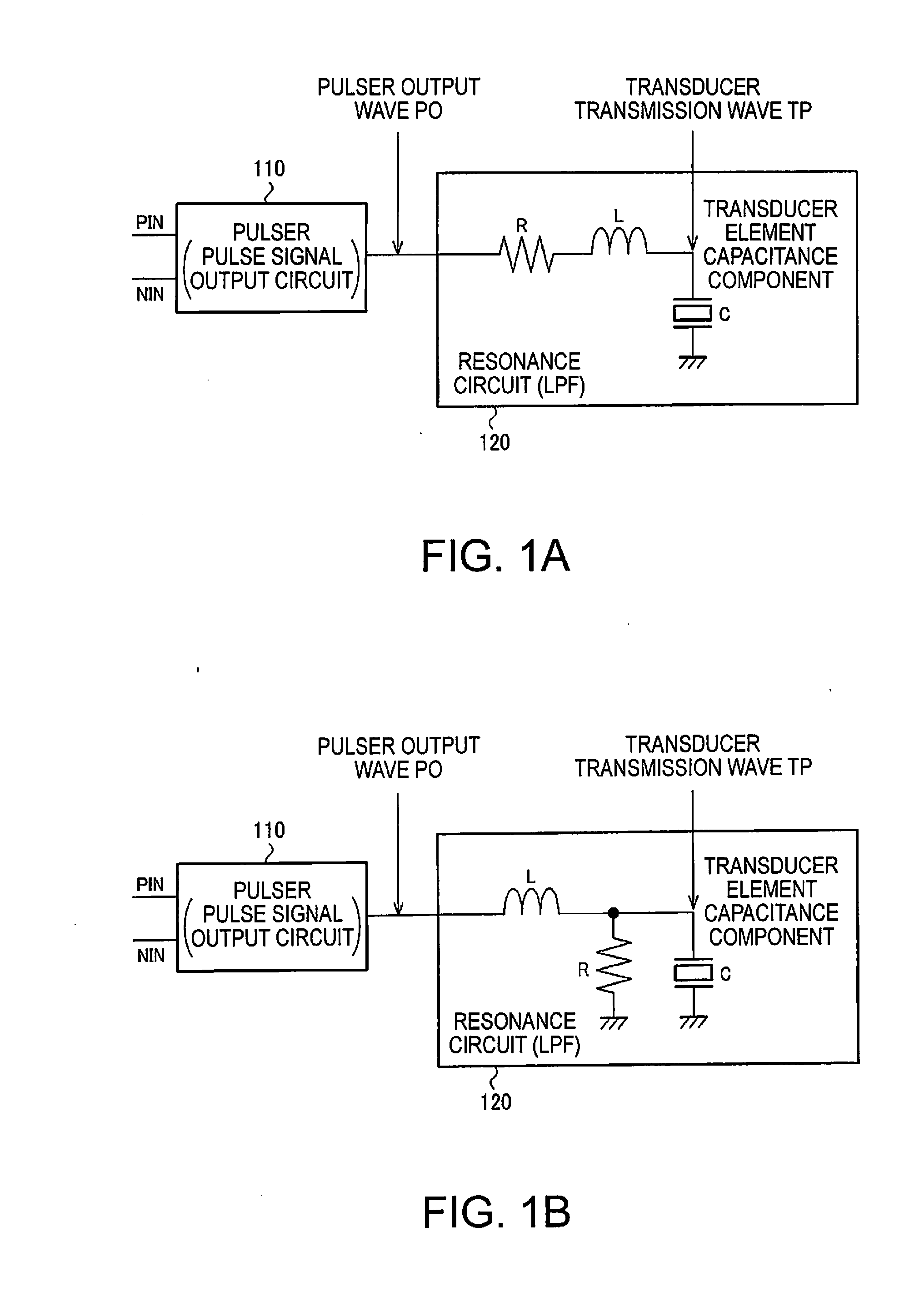
[0070]Hereinafter, FIGS. 1A and 1B illustrate examples of a configuration of a transmission circuit included in the ultrasonic measurement device 100 of the present embodiment. The transmission circuit shown in FIGS. 1A and 1B includes a pulser 110 (pulse signal output circuit 110), and a low-pass filter on the output side of the pulser 110. Furthermore, as described above, this low-pass filter constitutes, together with the ultrasonic transducer elements (vibrating elements), the resonance circuit 120.

[0071]FIG. 1A illustrates an example in which the low-pass filter LCR is configured by providing passive elements, which are an inductor L and a resistor R, in series to the ultrasonic transducer elements having a capacitance component C. The capacitance component C of the ultrasonic transducer elements also serves as a constituent component of the low-pass filter. Furthermore, in view of configuring the low-pass filter, it is also p...

second embodiment

3. Second Embodiment

[0119]In the above-described first embodiment, the transmission waveforms themselves are approximates to a sine wave curve, but in the present embodiment, by approximating the envelope curve of a transmission waveform to a sine wave curve, a harmonic component of the transmission wave is suppressed.

[0120]Conventionally, a method for generating a transmission waveform using a similar approach has been proposed, but in the conventional method, there are the problems that a control method is difficult, a plurality of voltage supplies are needed, and the like.

[0121]Therefore, in the present embodiment, the envelope curve of a transmission waveform is approximated to a (substantial) sine wave curve using a simple timing control of rectangular wave driving, without increasing the number of voltage supplies as compared to a predetermined number. Accordingly, the transient response of the transmission wave is shortened.

[0122]An example of a configuration of a system of t...


PUM


Abstract

An ultrasonic measurement device 100 includes a pulse signal output circuit 110 that outputs a pulse signal having a rectangular wave based on a clock signal, and a resonance circuit 120 that is connected to an output node of the pulse signal output circuit 110, includes an ultrasonic transducer element, and has frequency characteristics of a low-pass filter. Also, the pulse signal output circuit 110 outputs a plurality of pulse signals that are different from each other in at least one of pulse signal voltage, pulse signal width, and pulse output timing.

Description

BACKGROUND[0001]1. Technical Field[0002]The present invention relates to an ultrasonic measurement device, an ultrasonic imaging device and the like.[0003]2. Related Art[0004]As a device for use in examining the inside of a human body that serves as a test subject, an ultrasonic measurement device that emits an ultrasonic wave toward the subject and receives reflected waves from interfaces of objects having different acoustic impedances inside the subject draws an attention. The ultrasonic measurement device is also applied to diagnostic imaging that is performed on a superficial layer of the test subject to measure the visceral fat, the blood flow rate, and the like.[0005]When measurement using, for example, an ultrasonic measurement device is performed and a B-mode image is generated, it is necessary to reduce scatter noise caused when an ultrasonic echo (received wave) is received, in order to improve S / N of the received wave. Accordingly, it is preferable, for example, that a tr...

Claims


Application Information

Patent Timeline
IPC IPC(8): A61B8/08A61B8/14A61B8/00
CPCA61B8/5269A61B8/461A61B8/14A61B8/4483A61B8/4405A61B8/4427A61B8/54G01S7/5202G01S15/8913G01S15/8925B06B1/0215B06B2201/55B06B2201/76
Inventor ARAI, YOSHIO
Owner SEIKO EPSON CORP
Why Eureka
Try Eureka