High Capacity Structures and Monoliths Via Paste Imprinting

Active Publication Date: 2016-05-12
EXXONMOBIL UPSTREAM RES CO
View PDF1 Cites 27 Cited by
  • Summary
  • Abstract
  • Description
  • Claims
  • Application Information

AI Technical Summary

Benefits of technology

[0017]In some embodiments, the layering step can be layering a coated support onto a separate coated support to form layers of coated supports. In some embodiments, the layering step can inc

Problems solved by technology

This method is often hampered by clogging or poor coating results when the structures or channels on a support become too small.
In other words, monolith microstructures can reach a size below which applying the coating becomes impractical.
Decreasing the size of channels in a monolith leads to more surface area for reactivity, but there are limits to how smal

Method used


Image

  • High Capacity Structures and Monoliths Via Paste Imprinting
  • High Capacity Structures and Monoliths Via Paste Imprinting
  • High Capacity Structures and Monoliths Via Paste Imprinting

Examples


example 1

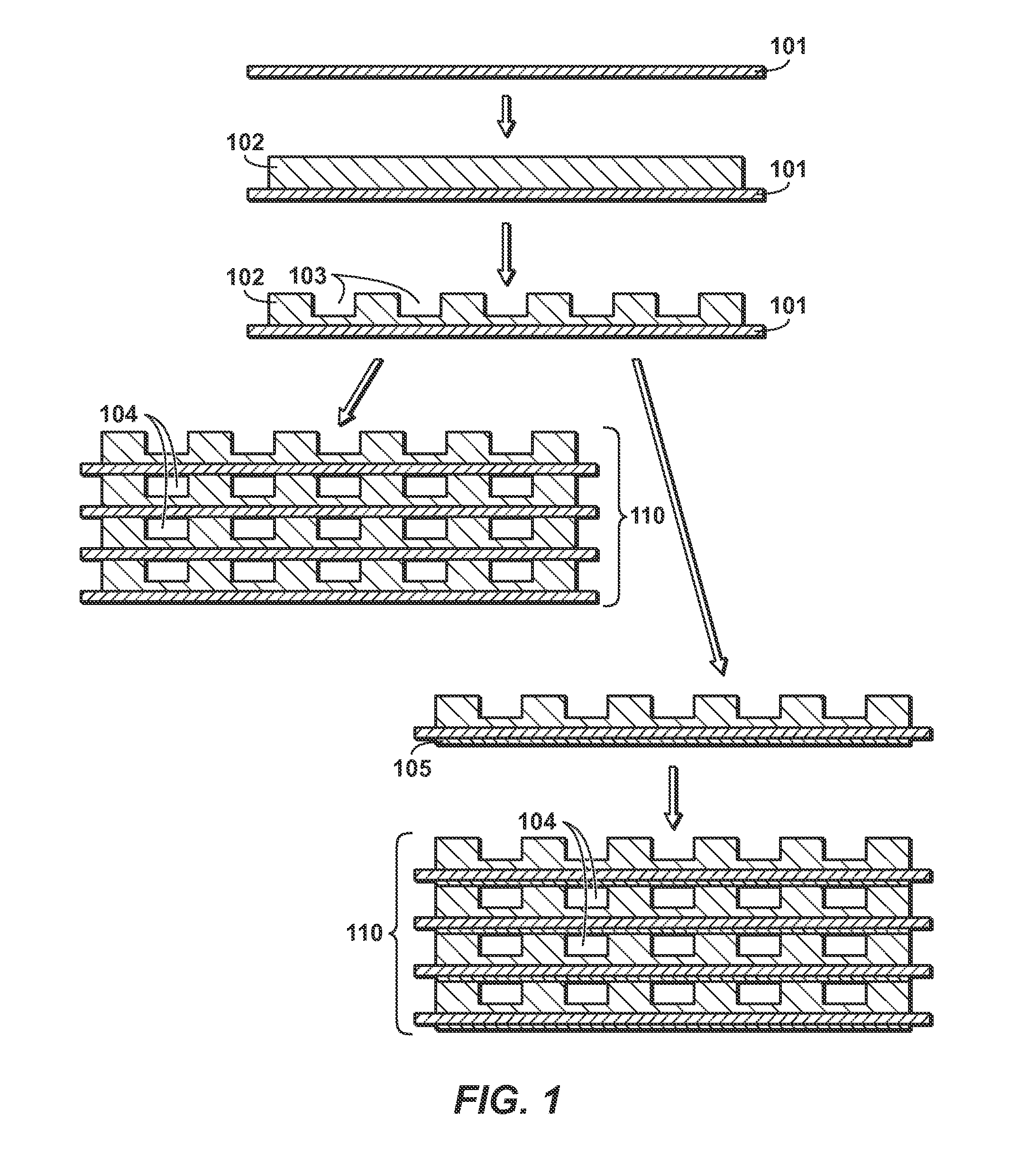
[0103]A coating method is demonstrated. Flat stainless steel foil (316 SS) was cleaned with a 10% bleach solution and calcined in air at 500° C. for 4 hours. After calcination, a thin coating (1-2 um) of Zirconium-based primer (80% Aremco Ceramabond 685-N, 20% H2O by weight) was applied to the surface of the foil via spray coating. The primer was allowed to set by heating the sample to 250° F. for 4 hours in air. The foil was then held flat and a thin layer of paste was applied to the surface. The paste contained a zeolite, colloidal silica binder, sodium silicate, water, and methyl cellulose polymer. The paste was allowed to briefly set (very slight drying). Then a piece of corrugated SS foil was treated with a release agent (e.g. WD40) and subsequently pressed into the thin layer of paste. The corrugated foil was then removed from the paste, leaving behind the inverse features of the corrugated foil. After air drying, the imprinted structure was then calcined at 400° C. for 4 hour...

example 2

[0105]A coating method is demonstrated. A corrugated SS foil was placed flat on a surface and treated with a release agent (e.g. WD40). Next a piece of oxidized and primed mesh, with same pretreatment as for the flat foil in Example 1, was placed directly on top of the corrugated foil. The paste from Example 1 was pressed through the mesh (similar to silk screening), and the paste filled the corrugations of the underlying foil while simultaneously coating the mesh. Upon drying, the mesh was lifted from the corrugated foil (the “mold”), and the imprinted features remain on the mesh. This integrated ceramic / metal structure can undergo bending to a degree required for rolling into a monolith, FIG. 12A. Further, the ceramic is completely integrated into the mesh, and can be seen encasing the mesh when embedded and viewed at the cross-sectional image in FIG. 12B. For purposes of scale, the dots in the cross-sectional image are the mesh wires with a 40 μm diameter.

example 3

[0106]An example of construction of a structure is demonstrated. A structure from Example 2 was fabricated to dimensions of 6″×60″. This was then calcined at 700° C. for 4 hours. The leading edge of the coated foil was tack-welded to an arbor of ½″ diameter. This arbor has screw holes in both ends so that it can be assembled into a winding device. The foil and arbor was assembled into the winding device such that the molded features of the substrate were pointing down, and the flat side facing upwards. Tension was applied to keep the substrate taught. The substrate was then saturated with water so the subsequent paste would not dry quickly when applied to the exposed flat side. A thin layer of paste of the same composition from Example 2 was applied to the exposed face of the foil as the foil was wound around the arbor. The resulting structure was then allowed to dry in air for 10 hours and then slowly heated in an oven ramped to 200° F. over 5 hours. Finally, the structure was then...


PUM

PropertyMeasurementUnit
Fractionaaaaaaaaaa
Fractionaaaaaaaaaa
Fractionaaaaaaaaaa

Abstract

The disclosure relate generally to structures, forms, and monoliths, and methods of preparing the same. This disclosure can produce uniform structured passageways or channels of active material, including adsorbent or catalyst, by imprinting or molding features into a paste on a support that can be subsequently assembled into a gas or liquid treating structure, i.e. a monolith. The paste, which can include an active material, binder, and other potential additives, can be applied to the support or pushed through a support (as in a mesh) as a thin film. The paste can be imprinted, stamped, shaped or otherwise handled to give features of desired height, shape, width, and positioning. When stacked or rolled, the features of one layer contact a subsequent layer, which seal to form passageways. The resulting structure can have high cell-density (>1000 cells per square inch) and a large volume fraction of active material.

Description

CROSS REFERENCE TO RELATED APPLICATIONS[0001]This application claims the priority benefit of U.S. Provisional Patent Application 62 / 077,977 filed Nov. 11, 2014 entitled HIGH CAPACITY STRUCTURES AND MONOLITHS VIA PASTE IMPRINTING, the entirety of which is incorporated by reference herein.TECHNICAL FIELD[0002]The various embodiments of the disclosure relate generally to structures and monoliths, prepared by coating a composite material onto a support, and layering supports together to form a layered assembly or structure. The composite material can have an active material in it, typically a catalyst or an adsorbent. The technology can be applied to prepare monoliths for gas adsorption, medium separations, or catalytic processes.BACKGROUND OF THE INVENTION[0003]Numerous processes and devices rely on monolithic structures acting as supports for a catalyst layer. Several methods are used to create the monolithic structures, the two main routes being ceramic extrusion and spiral wound foi...

Claims


Application Information

Patent Timeline
IPC IPC(8): B01J35/04B32B37/00B01J29/06B01J37/02B01J37/08B32B3/12B32B38/00
CPCB01J35/04B32B3/12B32B37/0076B32B2255/06B32B2311/00B01J37/0244B01J37/08B01J29/06B32B2255/20B32B38/0012C04B28/24C04B38/008C04B2111/00612C04B2111/00637C04B2111/0081C04B12/04C04B14/047C04B24/383B32B3/20B01J20/28035B01D53/04B01J37/0215
Inventor FOWLER, TRACY A.SMITH, THOMAS M.CUTLER, JOSHUA I.WALP, JENNA L.
Owner EXXONMOBIL UPSTREAM RES CO
Why Eureka
Try Eureka