Porous Polyolefin Fibers

a polyolefin fiber and porous technology, applied in the field of porous polyolefin fibers, can solve the problems of reducing the melt strength, breaking fibers, and low mechanical strength of products,

Active Publication Date: 2016-05-12
KIMBERLY-CLARK WORLDWIDE INC
View PDF2 Cites 7 Cited by
  • Summary
  • Abstract
  • Description
  • Claims
  • Application Information

AI Technical Summary

Problems solved by technology

This prevents the polymer from strain hardening, which typically occurs at temperatures well above the melting temperature or glass transition temperature of the polymer, yielding products with low mechanical strength.
This reduces the melt strength, thus leading to breaks in a fiber during spinning.

Method used


Image

  • Porous Polyolefin Fibers
  • Porous Polyolefin Fibers
  • Porous Polyolefin Fibers

Examples


example 1

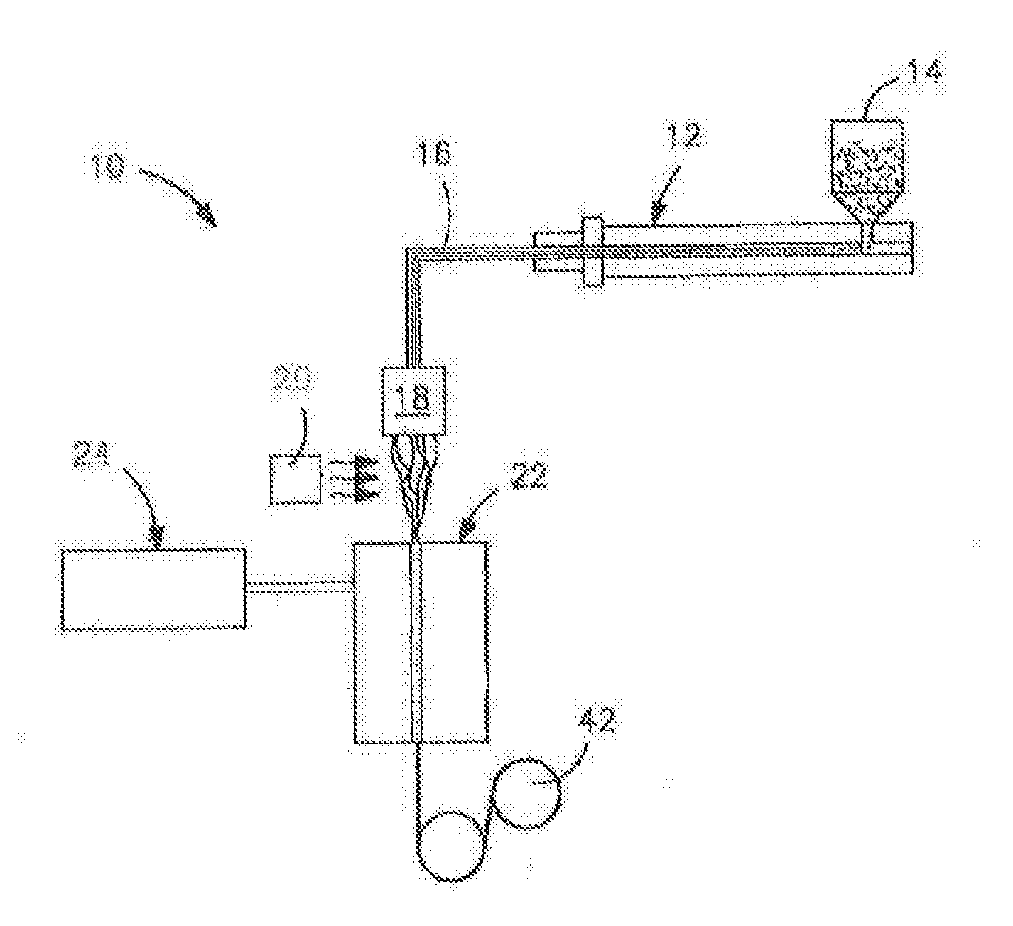
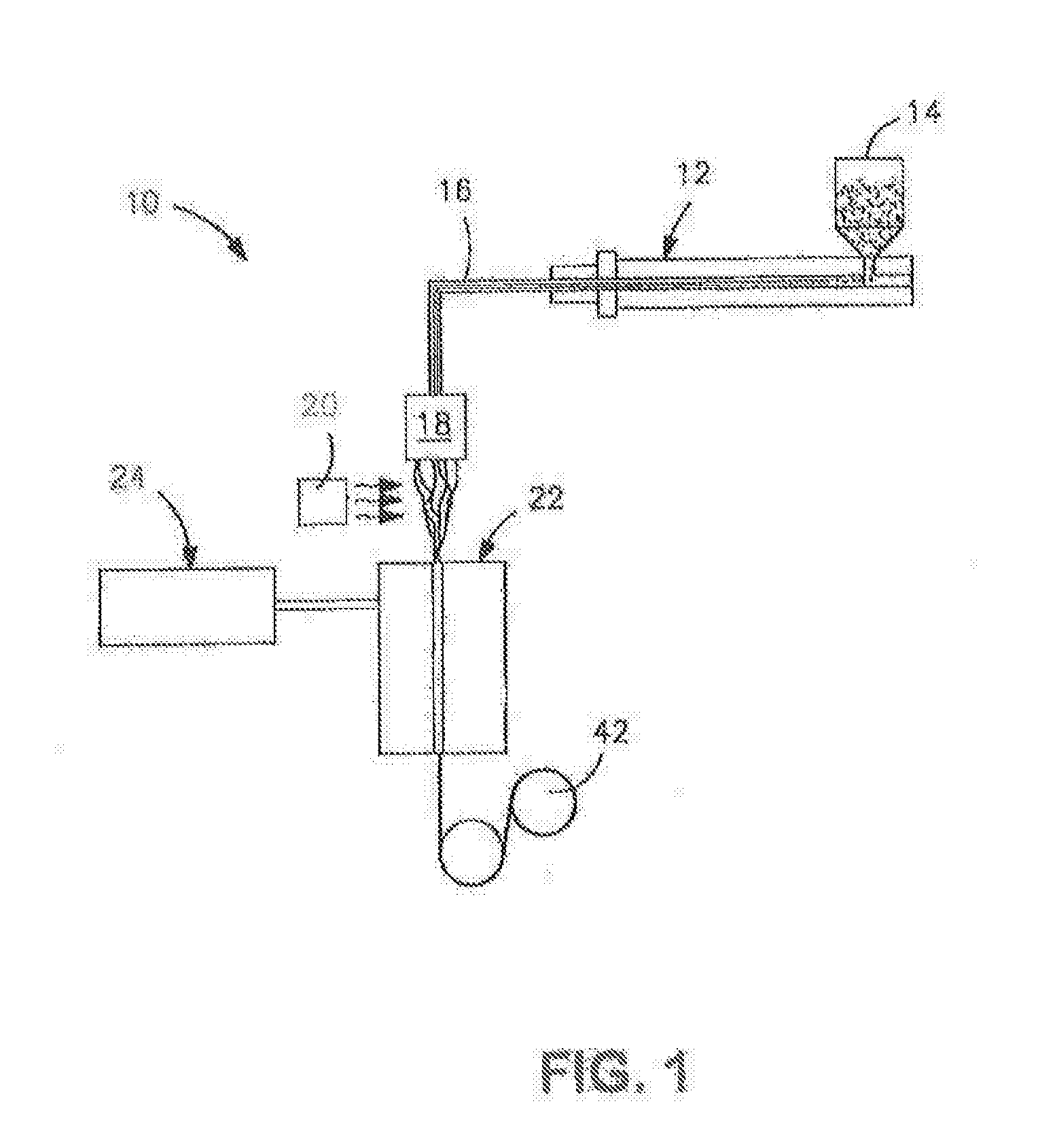
[0136]A precursor blend was formed from 91.8 wt. % isotactic propylene homopolymer (M3661, melt flow rate of 14 g / 10 at 230° C. and melting temperature of 150° C., Total Petrochemicals), 7.4 wt. % polylactic acid (PLA 6252, melt flow rate of 70 to 85 g / 10 min at 210° C., Natureworks®), and 0.7 wt. % of a polyepoxide. The polyepoxide was poly(ethylene-co-methyl acrylate-co-glycidyl methacrylate) (LOTADER® AX8900, Arkema) having a melt flow rate of 6 g / 10 min (190° C. / 2160 g), a glycidyl methacrylate content of 8 wt. %, ethyl acrylate content of 24 wt. %, and ethylene content of 68 wt. %. The components were compounded in a co-rotating twin-screw extruder (Werner and Pfleiderer ZSK-30 with a diameter of 30 mm and a L / D=44). The extruder had seven heating zones. The temperature in the extruder ranged from 180° C. to 220° C. The polymer was fed gravimetrically to the extruder at the hoper at 15 pounds per hour and the liquid was injected into the barrel using a peristaltic pump. The ext...

example 2

[0138]A blend of 93 wt. % polypropylene (Total M3661) and 7 wt. % Lotader® AX8900) were compounded in a co-rotating twin-screw extruder (Werne and Pfleiderer ZSK-30 with a diameter of 30 mm and a L / D=44). The extruder had seven heating zones. The temperature in the extruder ranged from 180° C. to 220° C. The polymer was feed gravimetrically to the extruder at the hoper at 15 pounds per hour. The extruder was operated at 200 revolutions per minute (RPM). In the last section of the barrel (front), a 3-hole die of 6 mm in diameter was used to form the extrudate. The extrudate was air-cooled in a conveyor belt and pelletized using a Conair Pelletizer. Fiber was then produced from the precursor blend using a Davis-Standard fiber spinning line equipped with a 0.75-inch single screw extruder and 16 hole spinneret with a diameter of 0.6 mm. The fibers were collected at different draw down ratios. The take up speed ranged from 1 to 1000 m / min. The temperature of the extruder ranged from 175°...

example 3

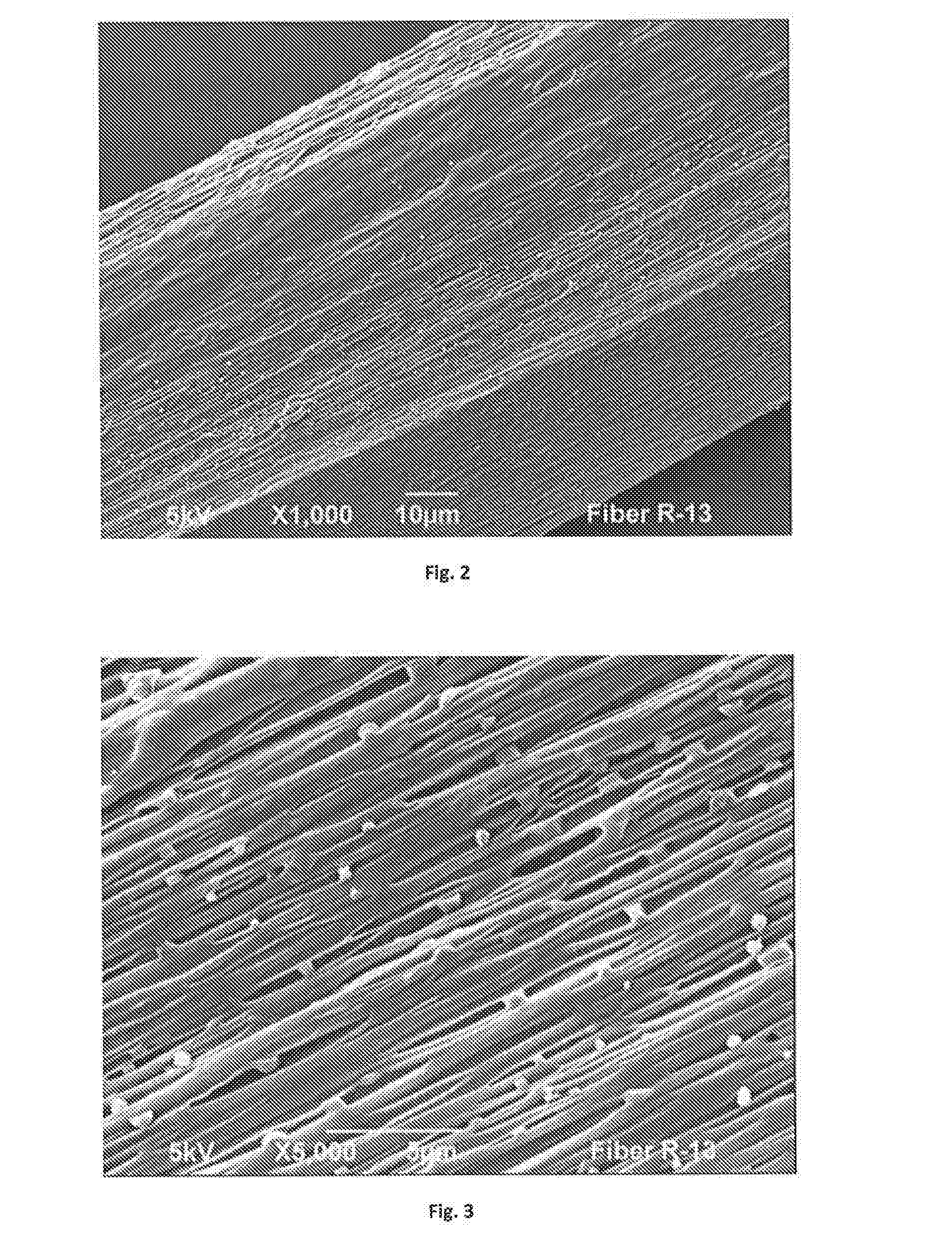
[0139]A blend of 91.1 wt. % polypropylene (Total M3661), 7.4 wt. % polylactic acid (NatureWorks 6251), and 1.5% Lotader® AX8900) were compounded in the extruder and the conditions described in Example 2. In this case, 5% of Pluriol® WI 285 was then injected to the barrel using a peristaltic pump. Fiber was then produced from the precursor blend using a Davis-Standard fiber spinning line equipped with a 0.75-inch single screw extruder and 16 hole spinneret with a diameter of 0.6 mm. The fibers were collected at different draw down ratios. The take up speed ranged from 1 to 1000 m / min. The temperature of the extruder ranged from 175° C. to 220° C. The fibers were stretched in a tensile tester machine at 300 mm / min up to 400% elongation at 25° C. To analyze the material morphology, the fibers were freeze fractured in liquid nitrogen and analyzed via Scanning Electron Microscope Jeol 6490LV at high vacuum. The results are shown in FIG. 7-8.


PUM

PropertyMeasurementUnit
melting temperatureaaaaaaaaaa
glass transition temperatureaaaaaaaaaa
temperatureaaaaaaaaaa

Abstract

A polyolefin fiber that is formed by a thermoplastic composition containing a continuous phase that includes a polyolefin matrix polymer and nanoinclusion additive is provided. The nanoinclusion additive is dispersed within the continuous phase as discrete nano-scale phase domains. When drawn, the nano-scale phase domains are able to interact with the matrix in a unique manner to create a network of nanopores.

Description

RELATED APPLICATIONS[0001]The present application claims priority to U.S. provisional applications Ser. Nos. 61 / 833,981, filed on Jun. 12, 2013, and 61 / 907,580, filed on Nov. 22, 2013, which are incorporated herein in their entirety by reference thereto.BACKGROUND OF THE INVENTION[0002]Significant efforts have been made to produce low density polyolefin fibers to improve the use of natural resources and reduction of the carbon footprint in finished products. A typical approach to producing low density polyolefin fibers is by foaming the polymer using physical or chemical blowing agents, which create gas cells though the bulk. Chemical blowing agents are compounds that undergo chemical reaction liberating gas that creates the cellular structure through the bulk of the polymer. Physical blowing agents are typically compressed gases that are dispersed in the polymer and expand creating the cells. Regardless, typical foaming process induce low molecular orientation because the cell form...

Claims


Application Information

Patent Timeline
Patent Type & Authority Applications(United States)
IPC IPC(8): D01F6/06D01F6/30B29C47/88B01J20/28B29C47/00C08J9/00B01J20/26B29C48/04B29C48/91
CPCD01F6/06C08J9/0061D01F6/30B01J20/261B01J20/28033B01J20/28042B29K2023/12B29C47/0042B29C47/0057B29C47/8805C08J2323/12C08J2323/14B01J20/28085B82Y30/00D01D5/247D01F1/08D01F6/04D01F6/46B29C48/04B29C48/0012B29C48/0018B29C48/91D01D5/24D01D1/10D01D5/34D04H1/4391B01D39/00B01J20/28011B01J20/28023B01J20/28028B01J20/3007D01F1/10D04H1/4291B01D69/087B01D69/141B01D71/26B01D71/46B01D71/48D01F8/06D01F8/14D01F8/16D02J1/224B01D2239/0618D10B2321/022D10B2401/10D10B2509/026A61F13/51A61F13/53A61L15/24A61L15/42A61F2013/51092A61L15/225A61L15/425
Inventor TOPOLKARAEV, VASILY A.MCENEANY, RYAN J.CARRILLO, ANTONIO J.MLEZIVA, MARK M.
Owner KIMBERLY-CLARK WORLDWIDE INC
Why Eureka
Try Eureka