In-situ on-line detection device and method for long-distance metallurgical liquid metal component

a liquid metal and detection device technology, applied in the field of long-distance online monitoring, can solve the problems of large amount of resources and energy resources, backward quality control, bulky detection equipment, etc., and achieve the effects of reducing the time of detection, and reducing the cost of detection equipmen

Active Publication Date: 2016-05-12
SHENYANG INST OF AUTOMATION - CHINESE ACAD OF SCI
View PDF29 Cites 12 Cited by
  • Summary
  • Abstract
  • Description
  • Claims
  • Application Information

AI Technical Summary

Benefits of technology

[0011]With respect to the defects in the prior art, the present invention provides an in-situ online detection device and method for metallurgical liquid metal component to provide timely and valid information for the quality control and a melting end, so that the detection time is greatly shortened, the detection distance can be adjusted extensively, the detection device can be flexibly installed and used,

Problems solved by technology

This time-consuming offline detection manner not only causes backward quality control, but also causes the waste of large amount of resources and energy resources.
Moreover, detection equipment is expensive, bulky and difficult to adapt to modern melting production requirements.
The short-distance laboratory equipment is accurate in measurement and short in time required (tens of seconds), but has enormous volume and higher requirement for the environment, so it cannot better adapt to the online monitoring of complex environments, such as steel factory, etc.
The device has shorter detection distance and relatively complicated structural design, can only measure a single element and cannot simultaneously measure multiple elements.
Because the character spectra of the light elements mainly focus on an ultraviolet re

Method used


Image

  • In-situ on-line detection device and method for long-distance metallurgical liquid metal component
  • In-situ on-line detection device and method for long-distance metallurgical liquid metal component
  • In-situ on-line detection device and method for long-distance metallurgical liquid metal component

Examples


Embodiment Construction

[0061]The present patent will be further described below in combination with the drawings and the embodiments.

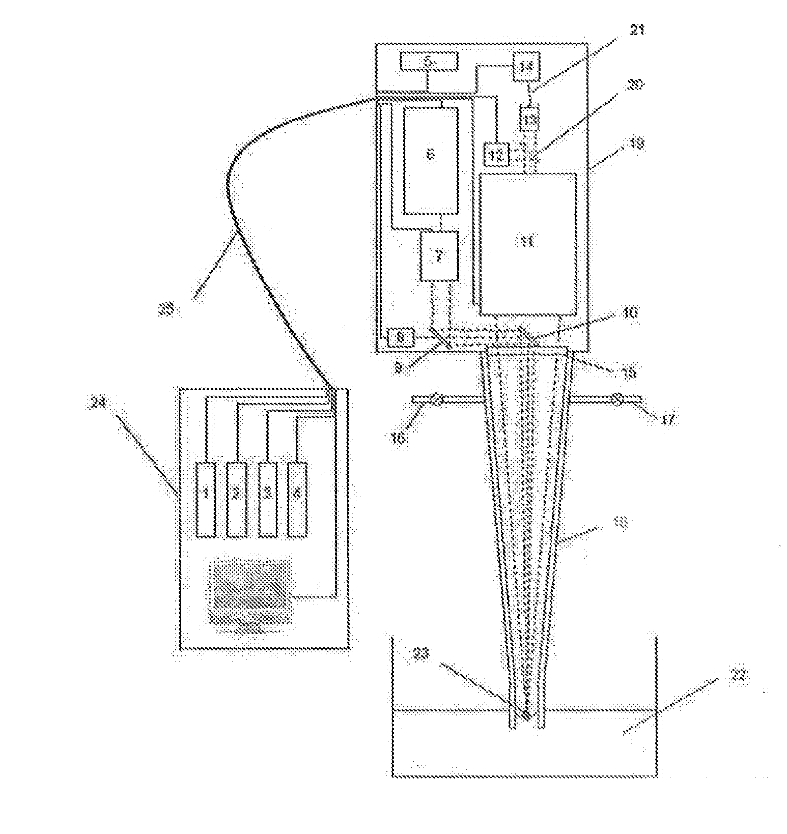
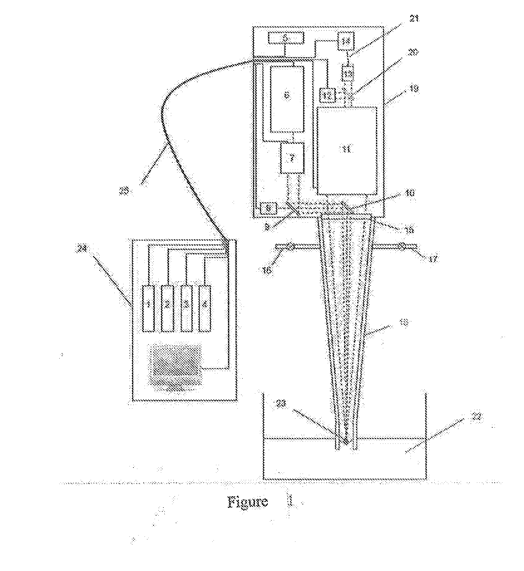
[0062]FIG. 1 shows an overall structural diagram of the present invention which comprises a front-end high-temperature resistant optical probe 18, a middle-end optical sensing device 19 and a back-end control platform 24, wherein:

[0063]The head of the front-end high-temperature resistant probe 18 is placed in metallurgical liquid metal 22; a sealed cavity body is formed internally; and inert gas is charged through the air pipe 16 to form an optical path environment of the inert gas; the middle-end optical sensing device 19 receives an operating signal of the back-end control platform 24; firstly, a distance from the metallurgical liquid metal surface 23 is measured through a laser distance measuring part 8; the first movable base 34 and the second movable base 37 in the remote beam expanding and focusing module 7 and the remote signal collecting module 11 are adjusted accord...


PUM


Abstract

An in-situ on-line detection device and detection method for a long-distance metallurgical liquid metal component. The detection device comprises a front-end high-temperature resistant probe (18), a middle-end optical sensing device (19) and a back-end control platform (24), wherein the head of the front-end high-temperature resistant probe (18) is placed in a liquid metal (22), the tail thereof is coaxially connected to the middle-end optical sensing device (19), and an optical window (15) is arranged in the connection position; and the middle-end optical sensing device (19) is connected to the hack-end control platform (24) through a signal line (25). The detection device and detection method can provide a timely and valid message for quality control and a melting end, so that the detection time is greatly shortened, the detection distance can he adjusted extensively, the measurement result is accurate, and it can he achieved to measure components that are difficult to measure such as C, S, P, etc.

Description

TECHNICAL FIELD[0001]The present invention relates to the technical field of long-distance online monitoring for high-temperature liquid component, in particular to an in-situ online detection device and method for long-distance metallurgical liquid metal component.BACKGROUND[0002]In the melting processes of metal and alloy, the change of chemical component is required to be detected, so as to control the product quality and judge a melting end. At present, due to the lack of an advanced and effective online measurement technology, the offline detection manner of manual sampling and sample preparation is generally adopted in the melting processes. For example, during the steel melting process, in the detection of high-temperature molten steel, the molten steel is required to be taken onto an analytical instrument for measurement and analysis after a series of processes of sampling, cooling, grinding, polishing, etc., and it needs to take 3 to 5 minutes in the entire process that wil...

Claims


Application Information

Patent Timeline
IPC IPC(8): G01N21/63G01N21/21G01N33/20G01B11/14
CPCG01N21/63G01B11/14G01N21/21G01N2201/0636G01N2201/06113G01N2201/0683G01N2201/088G01N33/206G01N21/718G01N21/8507G01N2021/695G01N33/205
Inventor SUN, LANXIANGYU, HAIBINXIN, YONGQI, LIFENGLI, YANGCONG, ZHIBO
Owner SHENYANG INST OF AUTOMATION - CHINESE ACAD OF SCI
Why Eureka
Try Eureka