Method for producing a low temperature glass phosphor lens and a lens produced by the same

a technology of glass phosphor and low temperature, applied in the field of lenses, can solve the problems of affecting the service life, the light emitting efficiency and stability, and the rapid deterioration of the lens, and achieving the effect of improving the lumen loss, and reducing the cost of production

Inactive Publication Date: 2016-05-19
TAIWAN COLOR OPTICS
View PDF7 Cites 9 Cited by
  • Summary
  • Abstract
  • Description
  • Claims
  • Application Information

AI Technical Summary

Benefits of technology

[0010]An objective of the present invention is to provide a method for producing a low temperature glass phosphor lens and a lens produced by the method. A thermally stable glass phosphor lens produced at a low processing temperature is, thus, provided.
[0019]The advantages of the method for producing a low temperature glass phosphor lens and the lens produced by the method are that the silica gel of the prior art is replaced with the glass material to mix and sinter with the fluorescent powder, forming a glass phosphor including characteristics of both of glass and fluorescence. Thus, the glass phosphor can be used as an LED packing material that is less easily to age under the heat energy from the chip of an LED. Furthermore, the processing temperature is controlled to be below 1000° C., which not only reduces the equipment costs but keeps the structure of the fluorescent powder in a stable state.

Problems solved by technology

Generally, if the heat generated during light emission of a light emitting diode cannot be guided to the outside, the temperature of the interface of the light emitting diode will become too high and, thus, adversely affect the service life, the light emitting efficiency, and stability.
For example, when a blue chip is used in a high luminance situation requiring a higher power, the heat generated on the surface of the blue chip causes rapid deterioration of the silica gel, leading to increased loss of lumen, severe chromaticity shift, and unstable quality of the lighting source.
However, the processing temperature of the glass materials are generally above 1000° C., which not only increases difficulties in the process but is apt to destruct the fluorescent property of the fluorescent powder during the high temperature process.

Method used


Image

  • Method for producing a low temperature glass phosphor lens and a lens produced by the same
  • Method for producing a low temperature glass phosphor lens and a lens produced by the same
  • Method for producing a low temperature glass phosphor lens and a lens produced by the same

Examples


Embodiment Construction

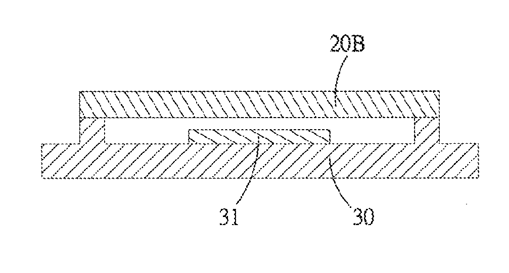
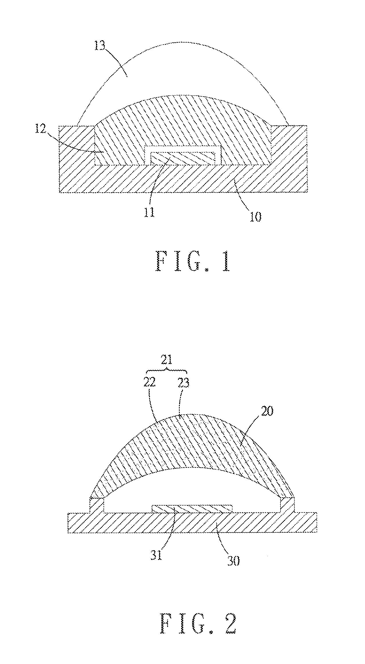
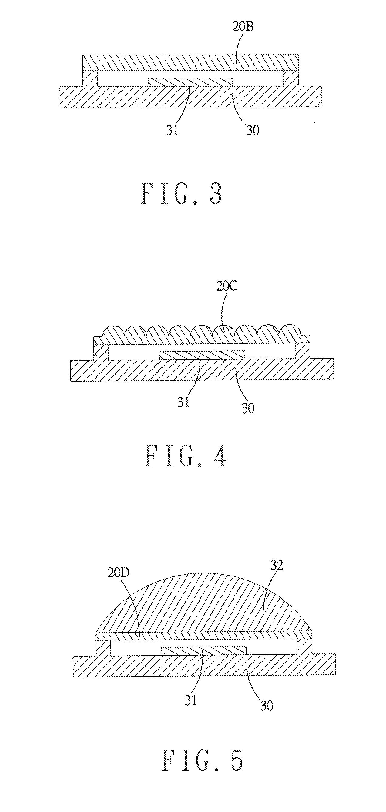
[0026]A method for producing a low temperature glass phosphor lens and a lens 20 produced by the method will now be set forth in connection with the accompanying drawings wherein like elements are designated by like reference numbers.

[0027]With reference to FIG. 2, the lens 20 is formed by a glass phosphor 21. The glass phosphor 21 is formed by sintering a glass material 22 and fluorescent powder 23. The fluorescent powder 23 is a fluorescent material selected from the group consisting of yttrium aluminum garnet (YAG), nitride, and silicate. The glass material 22 is selected from the group consisting of a silicate system, a phosphor system, a borate system, and a tellurate system.

[0028]Diffusion can be reduced when the stable crystalline structure of the fluorescent powder including yttrium aluminum garnet is sintered together with amorphous soda glass, maintaining good optical characteristics. Furthermrore, addition of nitride and silicate increases the color rendering index (Ra). ...


PUM

PropertyMeasurementUnit
diameteraaaaaaaaaa
temperatureaaaaaaaaaa

Abstract

A method for producing a low temperature glass phosphor lens includes dry mixing a glass material and fluorescent powder to form a powdery or particulate mixture. The mixture is grinded to a diameter of 15-20 μm, obtaining uniformly mixed glass fluorescent powder. The glass fluorescent powder is hot pressed into a glass phosphor at a temperature of 500-1000° C. The glass phosphor is grinded and polished into a lens. The fluorescent powder can be a fluorescent material selected from the group consisting of yttrium aluminum garnet, nitride, and silicate. The glass material can be selected from the group consisting of a silicate system, a phosphor system, a borate system, and a tellurate system. The glass phosphor includes characteristics of both of glass and fluorescence. The glass phosphor can keep efficiency under the high heat generated by the chip of an LED.

Description

BACKGROUND OF THE INVENTION[0001]1. Field of the Invention[0002]The present invention relates to a lens that can be used in a white light illuminating module or used as a packaging structure of a light-emitting diode.[0003]2. Description of the Related Art[0004]Recently, white light emitting diodes have gradually replaced conventional lights and have received attention from the consumers due to the advantages of long service life, small volume, and excellent light emitting efficiency.[0005]FIG. 1 shows a conventional white light emitting diode including a substrate 10, a short wavelength light emitting diode 11 mounted on the substrate 10, a color change medium 12 mounted on the short wavelength light emitting diode 11, and a packing element 13 for packaging the color change medium 12 and the short wavelength light emitting diode 11. The short wavelength light emitting diode 11 emits short wavelength light rays. The color change medium 12 is excited by the short wavelength light ray...

Claims


Application Information

Patent Timeline
Patent Type & Authority Applications(United States)
IPC IPC(8): G02B1/02F21V5/00C03B19/06C03C4/12C09K11/02C09K11/77C03C3/087F21V5/04C03C19/00
CPCG02B1/02F21V5/04F21V5/004C03B19/063C03C2204/00C09K11/025C09K11/7706C03C3/087C03C4/12C03C19/00C03C3/095H01L33/501G02B3/00H01L33/50
Inventor CHENG, WOOD-HICHANG, YUNG-PENGCHEN, LI-YINTSAI, CHUN-CHINHUANG, YI-CHUNGCHENG, WEI-CHIHCHANG, JIN-KAI
Owner TAIWAN COLOR OPTICS
Why Eureka
Try Eureka