
Plant growth system

a growing system and plant technology, applied in the direction of instruments, computer control, renewable energy machines, etc., can solve the problems of increased pressure, difficult disposal of waste water containing such nutrients, and high cost of nutrient acquisition, so as to reduce the flow speed

Active Publication Date: 2016-05-26
ROCKWOOL AS
View PDF63 Cites 29 Cited by
  • Summary
  • Abstract
  • Description
  • Claims
  • Application Information

AI Technical Summary

Benefits of technology

This patent describes a system for measuring and controlling the growth conditions of plants or substrates using a central processing unit. By measuring properties and sending them to a central unit, the system can adjust the growth conditions in real-time based on new data or environmental factors. The system can use detectors and is preferably wireless in its deployment. The orientation of the fibers in the system can affect the flow speed of liquid and reduce spilling. The technical effects of this system include greater flexibility, accuracy, and control over growth conditions.

Problems solved by technology

This is both for cost and environmental reasons.
In particular, the nutrients are expensive to obtain, while waste water containing such nutrients is difficult to dispose of due to environmental legislation.
These pressures will increase as raw materials (particularly fertilisers such as phosphates) become increasingly scarce.
In practice, existing growing methods and / or substrates provide limitations on both these aspects.
As would be expected, sub-optimal water retention in the substrate can lead to either a shortage or an excess of water.
In the case of shortage, this leads to water being lost, and thus wasted, through the drain hole.
If water fails to reach the roots, this will result in loss of growth speed and thus loss in production.
In particular, in order to ensure that the plant roots in the top region of the slab are sufficiently watered, it may be necessary for the grower to provide excessive water to the slab to maintain sufficient water around the roots, leading to greater wastage through the drain hole and extra costs.
Excessive water levels can also increase the risk of fungal growth on one hand or oxygen depletion on the other which may damage the plant.
Although the nutrients are typically introduced with the water, they will not necessarily be distributed and retained by the slab in the same way.
If nutrients are poorly distributed, or are lost from the slab, then excess nutrients may be required in the slab as a whole for the plant to receive the nutrients it requires.
This is of course a waste of nutrients.
Moreover, in some examples a build-up of nutrients if they are not replaced can reach levels which can cause dehydration or are at least non-ideal for plant growth.
However, although such techniques can provide useful information to the grower, they do not in themselves ensure improved water, nutrient and oxygen content and distribution within the slab.
Further, implementation of such systems can require multiple instances of expensive components to be installed at relatively high expense to the user, and redeployment of those systems, to save costs in measuring multiple areas or growing systems can be time consuming and labour intensive.
Although such systems and devices can provide useful information about agricultural soil composition and can help with the automation of irrigation of the soil, they do not provide solutions for effective management of water and water / nutrient distribution in hydroponic growing systems such as mineral wool substrates.
Existing techniques often result in the loss and / or overfeeding of water and / or nutrients as they are unable to offer suitable and flexible monitoring and control of growing conditions, nor sufficiently accurate and adjustable response strategies and reconfiguration of existing systems can be labour intensive and can induce errors due to the numerous steps involved in reconfiguring individual elements of a system separately and individually.

Method used


Image

  • Plant growth system
  • Plant growth system
  • Plant growth system

Examples


Embodiment Construction

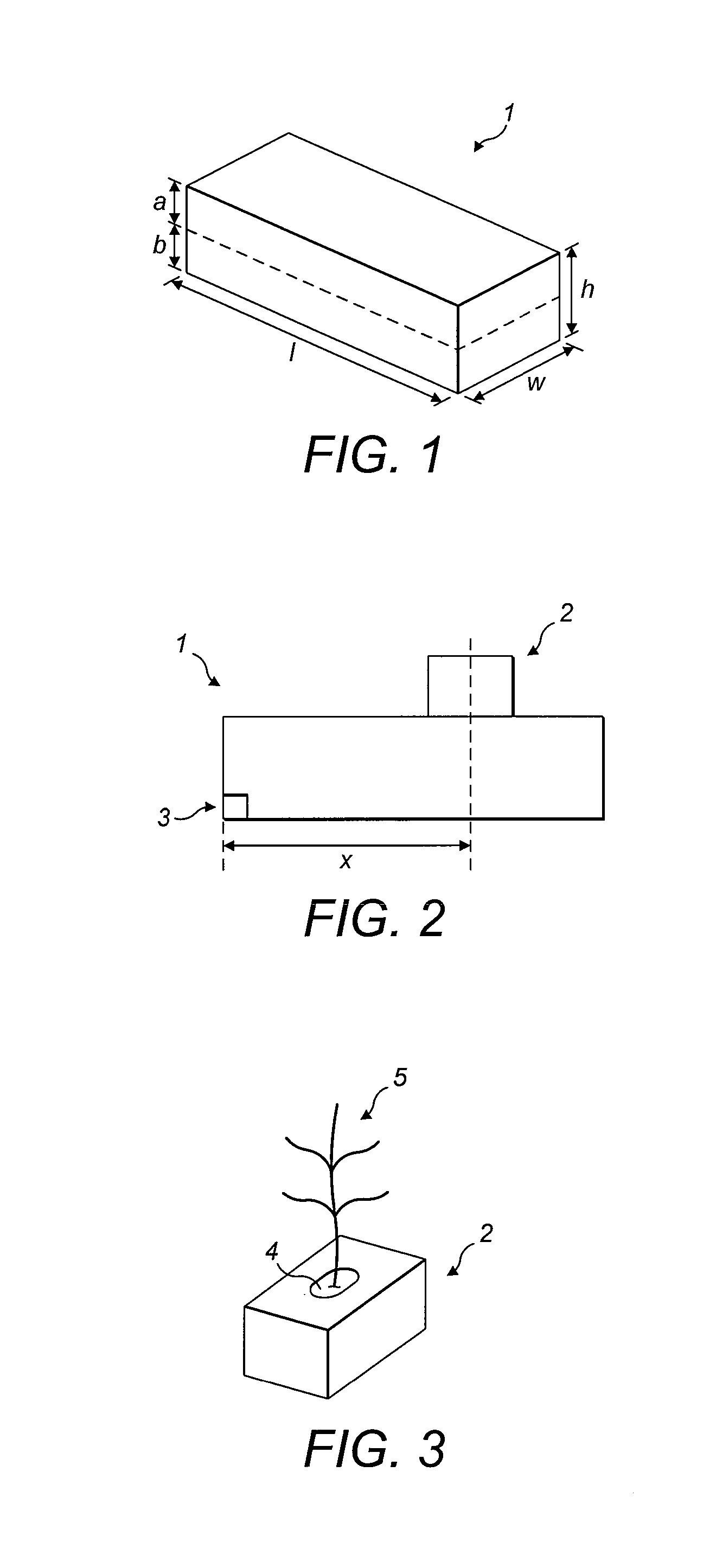
[0104]Referring to FIG. 1, there is shown a mineral wool slab 1 having a first layer of a first density disposed above a second layer of a second density. The slab 1 has a volume of 6.8 litres, although more generally for preferred embodiments the volume may be in the range of 3 litres to 20 litres, more preferably in the range 5 litres to 15 litres, and most preferably in the range 5 to 11 litres. Some embodiments comprise a slab with a volume in the range 6 litres to 8 litres. In other embodiments, the volume may lie in the range of 3 litres to 15 litres, or 3 litres to 10 litres, for example. An alternative preferred embodiment comprises a slab having a volume of 9 litres. The slab may comprise multiple layers, including a bottom layer and a top layer, whose growth conditions may vary relative to one another.

[0105]As is the case in the embodiment shown in FIG. 1, it is preferable that the height of the bottom layer is greater than that of the top layer. For example, the ratios be...


PUM


Abstract

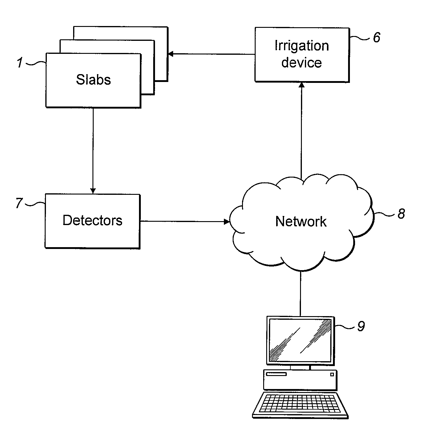
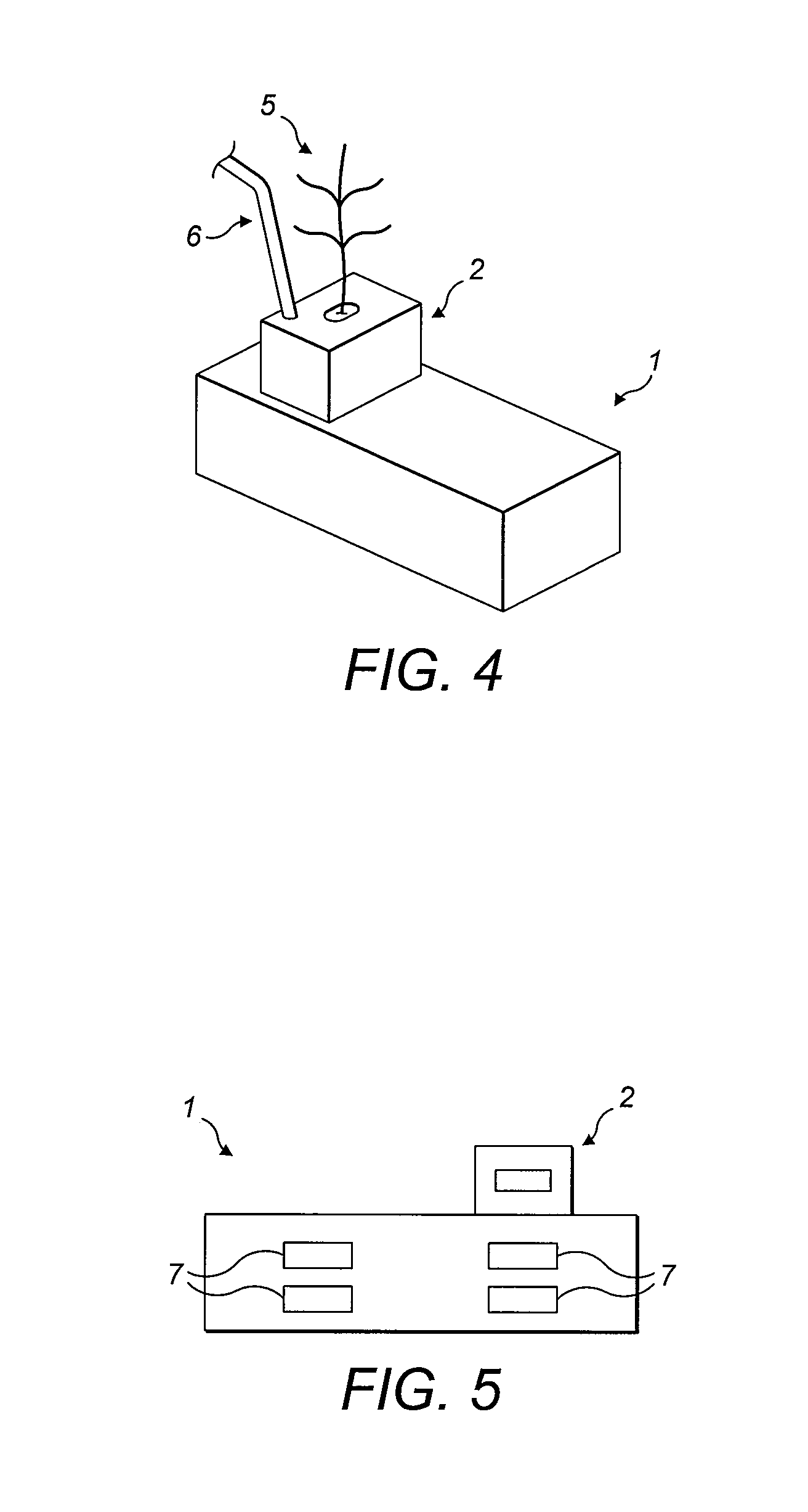
A system and related method for monitoring plant growth conditions is provided, comprising a plurality of detectors (7) and central detector data processing means (1103); each detector (7) being arranged to measure properties indicative of a temperature, a water content, and a nutrient content, of a plant growth substrate; each detector (7) being further arranged to transmit the measured property or properties over a communications link to the central detector data processing means (1103); the central detector data processing means (1103) being arranged to store predefined irrigation data, defining a relationship between plural values for temperature, water content, pH level and / or nutrient content of the plant growth substrate; and plural desired irrigation output values; process the measured properties from each detector (7) to determine calculated properties of the substrate; and provide an output indicative of a desired irrigation input for the growth substrate, based upon measured properties received from the detectors (7) and the predefined irrigation data. A portable detector communications device (1105) for communicating configuration data relating to the detectors (7) may be included in the system.

Description

FIELD OF THE INVENTION[0001]The present invention relates to the growth of plants in hydroponic growing systems, including artificial substrates. In particular, but not exclusively, the present invention relates to a system and method for monitoring plant growth conditions, more particularly plant growth conditions in mineral wool substrates used for plant growing.BACKGROUND TO THE INVENTION[0002]Hydroponic growing systems are known in the art for the purpose of growing plants using mineral nutrient solutions, without soil (i.e. soilless cultures). Plants in hydroponic growing systems may be grown in substrates of various types, such as mineral wool, glasswool, cocopeat (coir), or peat slabs, for example.[0003]It is known that plants can be grown in mineral wool growth substrates. Such growth substrates are typically provided as a coherent plug, block, slab or mat / blanket and generally include a binder, usually an organic binder, in order to provide structural integrity to the produ...

Claims


Application Information

Patent Timeline
IPC IPC(8): A01G9/24G05B15/02A01G25/16
CPCA01G9/24G05B15/02A01G25/16A01B79/005A01G31/02A01G24/18Y02P60/12Y02P60/21A01G27/005A01G31/00A01G9/124
Inventor DE GROOT, JACOB FRANKVAN DER VEEN, DOLFHEMPENIUS, EELKE GJALT
Owner ROCKWOOL AS
Learn More