Device and method for separating dirt particles from the working medium of a turbine

a technology of working medium and dirt particles, which is applied in the direction of machines/engines, liquid fuel engines, separation processes, etc., can solve the problems of cost saving, achieve the effect of simple and efficient, increase the rotational speed of the working medium containing dirt particles, and permanent reduction of the concentration of dirt particles in the working medium

Active Publication Date: 2016-05-26
ROBERT BOSCH GMBH
View PDF4 Cites 2 Cited by
  • Summary
  • Abstract
  • Description
  • Claims
  • Application Information

AI Technical Summary

Benefits of technology

[0008]A further advantage results from an inside radius of the hollow body which decreases along the principal axis between the supply line and the outflow wall located opposite the pipe. This is advantageous because the rotational speed of the working medium containing the dirt particles increases; thus enabling the dirt particles to be thrown more strongly against the walls of the hollow body due to the higher centrifugal force and to thereby be decelerated so that they can more easily separate themselves from the flow.
[0009]The arrangement of at least one bore on the outflow wall of the hollow body that is opposite the pipe is advantageous. The dirt particles can be removed in a simple and efficient way from the swirl generator by means of an outlet line connected to the bore. This can, e.g., be implemented by the buildup of a pressure gradient.
[0010]Especially in the case of a turbine, which is disposed in a system for heat recovery in an internal combustion engine, an arrangement of a swirl generator directly upstream of the turbine for separating dirt particles from the working medium is advantageous. In the system for heat recovery in an internal combustion engine, the working medium flows through a circuit in which at least one heat exchanger, the turbine, at least one condenser and at least one pump are disposed in succession. The working medium therefore flows through the turbine a number of times and is not replaced for each passage through the turbine, as is the case in other applications as, e.g., in the case of a turbocharger or in a thermal power plant for industrial applications. As a result of the circular process within the system for heat recovery in an internal combustion engine, the working medium becomes permanently contaminated by dirt particles, as, e.g., lubricants. The dirt particles can cause damage to the turbine or other components of the aforementioned system for heat recovery as a result of erosion, deposition or droplet impact. A reduction in the dirt particles in the working medium occurs by means of the proposed device and the proposed method before each passage of said working medium through the turbine. The concentration of dirt particles in the working medium can therefore be permanently reduced.

Problems solved by technology

In addition, costs are saved due to the multiple use of the same component, e.g. housing being used as pipe.

Method used


Image

  • Device and method for separating dirt particles from the working medium of a turbine
  • Device and method for separating dirt particles from the working medium of a turbine
  • Device and method for separating dirt particles from the working medium of a turbine

Examples


Embodiment Construction

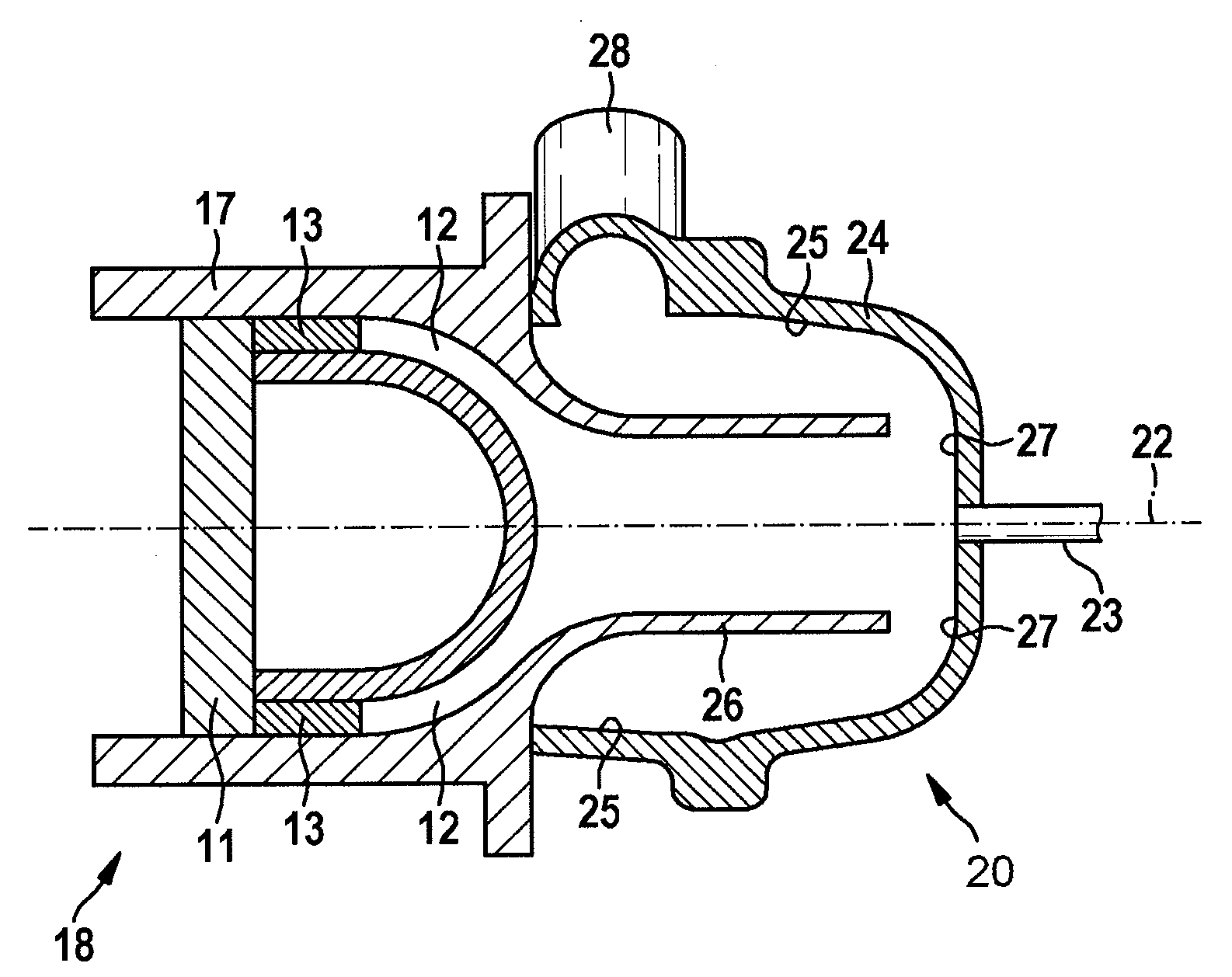
[0016]A turbine 10 comprising a rotor 11, which is disposed in a housing 17, is shown in FIG. 1. A working medium, which is used to drive the turbine, arrives at the rotor 11 via a supply line 12, said rotor being set in a rotational movement by the working medium. The kinetic energy of the rotor 11 can be converted into further energy forms.

[0017]A nozzle arrangement 13 can be disposed upstream of the rotor 11. This can be a laval nozzle which leads to an acceleration of the working medium prior to striking the rotor 11.

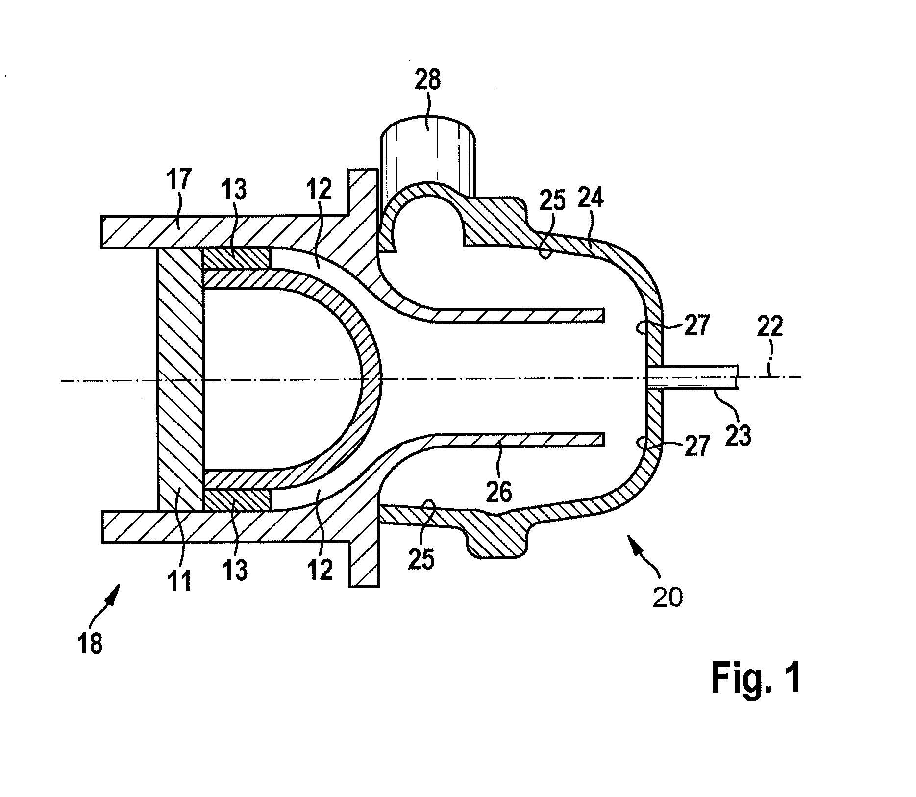
[0018]A swirl generator 20 is disposed directly on the input side of the turbine 10. The swirl generator 20 is formed from a hollow body 24 which is approximately rotationally symmetrical and which is fastened to the front face of the housing 17 of the turbine 10. The hollow body 24 has an inlet line 28. The working medium can move into the hollow body 24 of the swirl generator 20 by means of the inlet line 28. On account of the inlet line 28, the rotational symmetr...


PUM

PropertyMeasurementUnit
speedaaaaaaaaaa
inside radiusaaaaaaaaaa
inertiaaaaaaaaaaa

Abstract

The invention relates to a device and a method for separating dirt particles from the working medium of a turbine (10). The turbine (10) comprises at least one rotor (11) which is arranged in a housing (17). A swirl generator (20) is provided that sets the working medium and the dirt particles in a spiral-shaped rotational movement along a principal axis (22) by means of the geometry of the swirl generator (20) and thereby separates the dirt particles from the working medium. The swirl generator (20) is designed in such a way that the working medium experiences a reversal of the speed component parallel to the principal axis (22) within the swirl generator (20).

Description

BACKGROUND OF THE INVENTION[0001]The invention relates to a device and method for separating dirt particles from the working medium of a turbine.[0002]The European patent publication EP 2 137 397 B1 discloses an arrangement for supplying an internal combustion engine with a stream of combustion air and for removing a stream of exhaust gas, in which arrangement a swirl generator is designed as a centrifugal separator for condensate forming in the exhaust gas return stream. An effective separation can be brought about without additional measures by using the centrifugal forces or, respectively, mass inertia forces which occur anyway in the swirl generator and act on condensate that has formed.[0003]A turbocharger for an internal combustion engine is known from the German patent publication DE 10 2007 030 277 A1. A centrifugal separator, which is coupled to the shaft, is disposed between a compressor wheel and the turbocharger in an intermediate chamber. The centrifugal separator is us...

Claims


Application Information

Patent Timeline
Patent Type & Authority Applications(United States)
IPC IPC(8): F01D25/32F01K25/14F01K11/00F01D9/02F01D15/08F01D25/08F01D5/02B01D45/16F01K23/06
CPCF01D25/32B01D45/16F01K25/14F01K11/00F01K23/065F01D15/08F05D2260/20F01D5/02F01D9/02F05D2220/30F05D2210/12F05D2240/24F01D25/08B01D45/12B01D45/14
Inventor WENGERT, ANDREASMAGEL, HANS-CHRISTOPHEISENMENGER, NADJARUECKERT, FRANK ULRICH
Owner ROBERT BOSCH GMBH
Why Eureka
Try Eureka