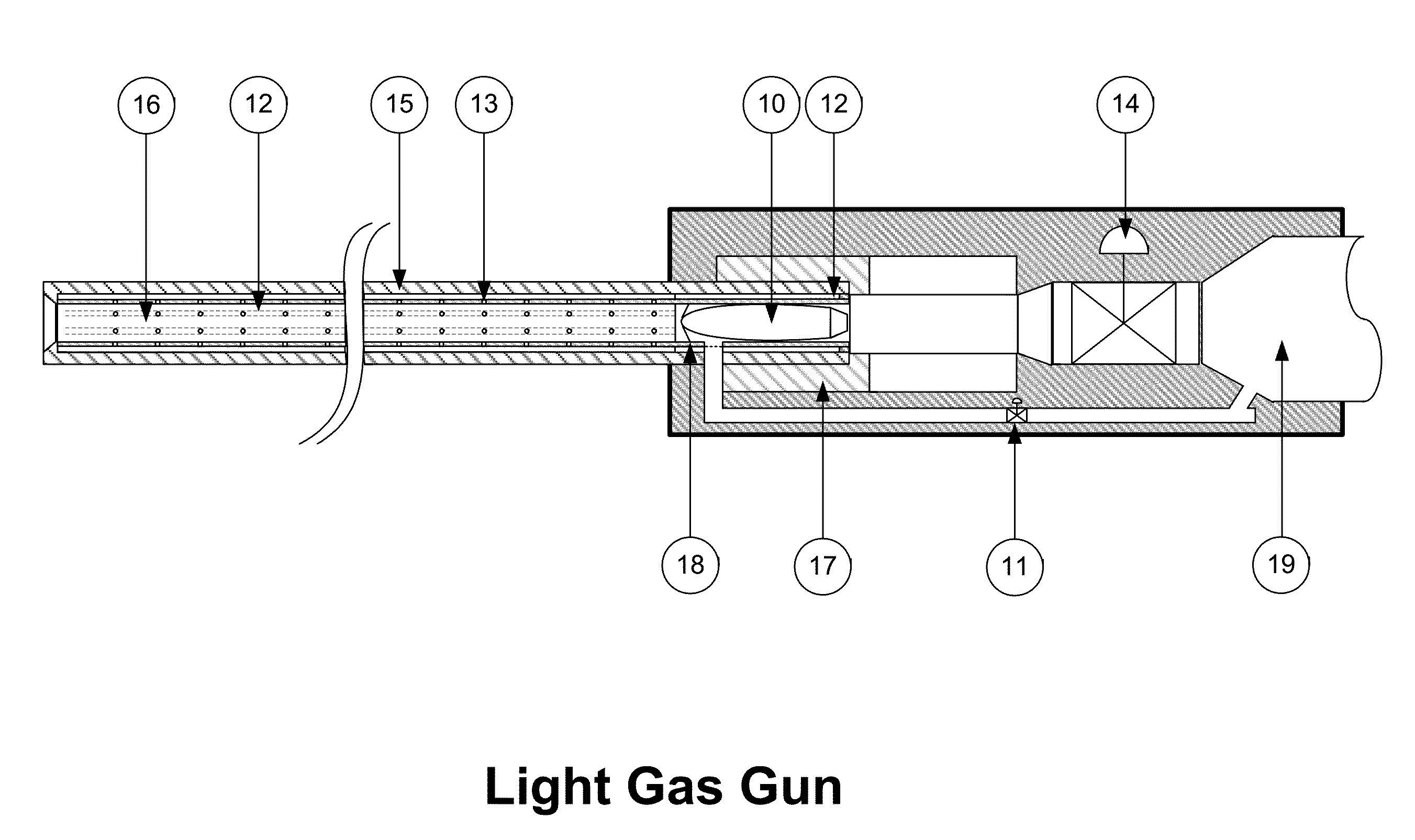
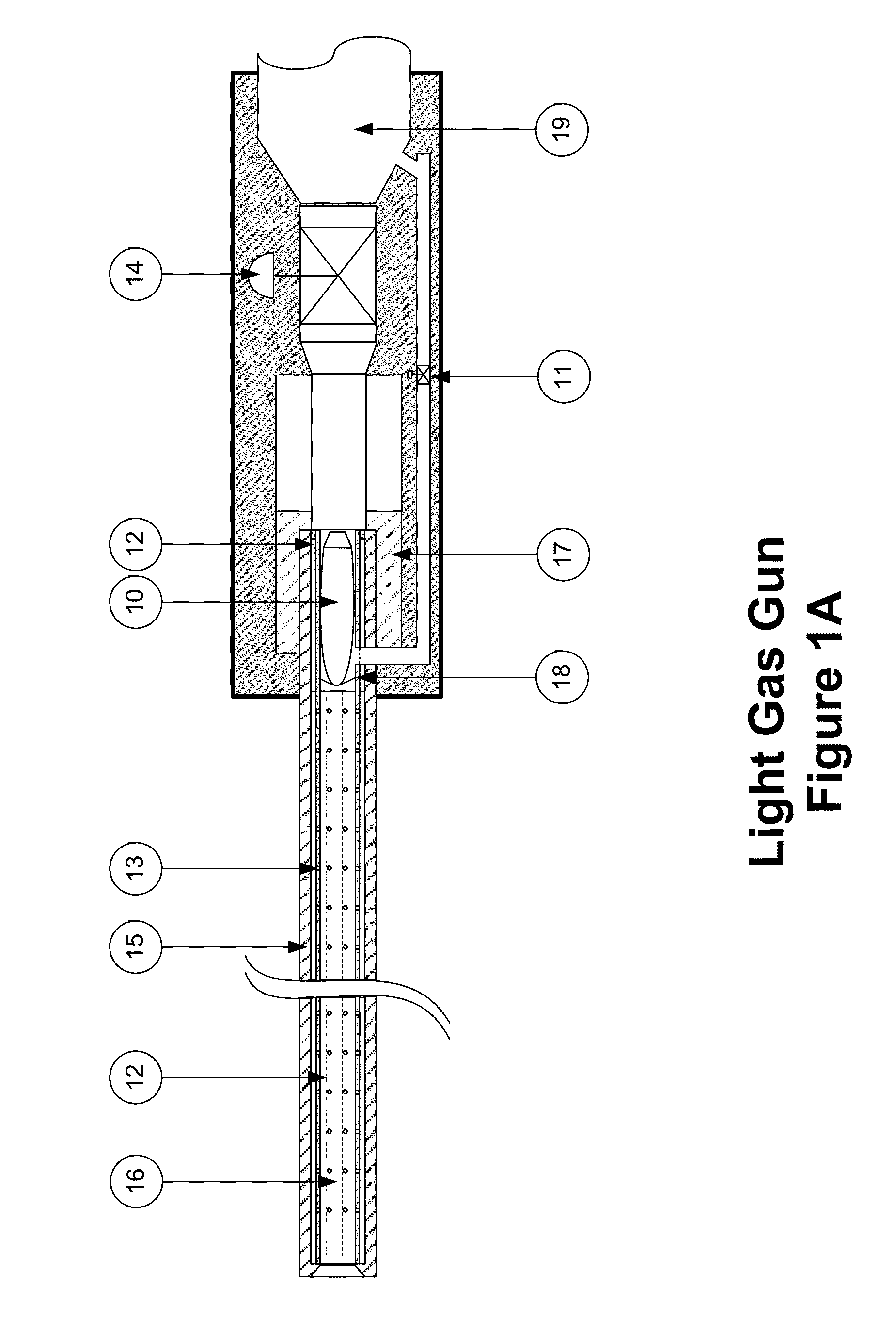
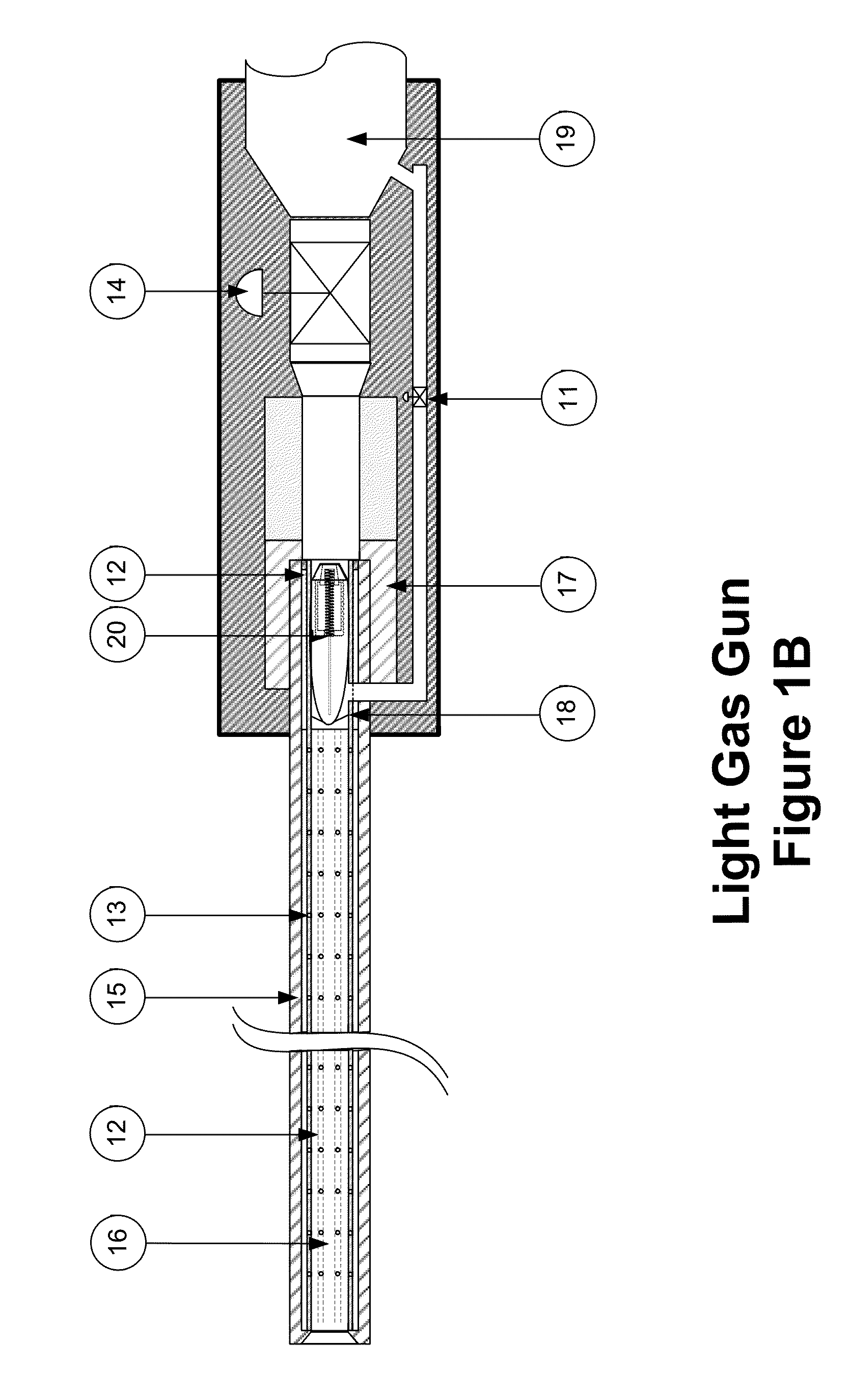
Light Gas Gun
a gas gun and light technology, applied in the field of light gas guns, can solve the problems of increasing range and lethality, and achieve the effects of increasing range, reducing the drag of the projectile, and increasing the energy on the targ
- Summary
- Abstract
- Description
- Claims
- Application Information
AI Technical Summary
Benefits of technology
Problems solved by technology
Method used
Image
Examples
first embodiment
[0079]The projectile 10 is loaded into the breech assembly FIG. 4 by opening the receiver locking bolt 17, inserting the projectile 10, then closing and locking the receiver locking bolt 17. With the projectile 10 loaded, the trigger signal is activated, first opening the purge valve 20 for sufficient time to purge the barrel of air and replacing it with light gas, then the trigger valve 14 is opened and the purge valve 20 is closed simultaneously. Light gas entering the breech 38 from the trigger valve 14 propels the projectile 10 down the barrel. A light gas pressure wave also travels the channels 12 on the outside of the inner tube 15 and enters the inner tube 15 through the gas bearing ports 13, creating a vortex in the barrel that imparts a spin on the projectile 10 as it travels down the barrel. The light gas travels the channels 12 faster than the pressure wave behind the projectile 10, allowing the light gas to flow through the gas bearings to impinge upon the projectile 10 ...
second embodiment
[0080]The second embodiment is identical to the first with two exceptions. The projectile assembly 20 is substituted for the known projectile 10. The channels 12 and gas bearing ports 13 are cut and drilled normal to outside wall of the inner tube 15, as it is no longer necessary to impart spin on the projectile assembly 20.
[0081]The projectile assembly 20 is loaded in the same fashion as in the first embodiment. When the light gas gun is fired, the pressure behind the projectile assembly 20 increases rapidly. The spring loaded valve 40 in the aft projectile body 41 of the projectile assembly 20 opens as the pressure external to the projectile assembly 20 is greater than the internal pressure plus the compression strength of the projectile spring 43. The spring loaded valve 40 closes as the internal and external pressures equalize. The forward and aft projectile bodies 42 / 41, as well as the spring loaded valve 40, are constructed of sintered metal. With high pressure light gas store...
third embodiment
[0084]In the third embodiment, the necessity to purge the barrel assembly FIG. 2B is eliminated by adding a muzzle valve assembly FIG. 3 on the muzzle end of the barrel assembly FIG. 2B. The muzzle valve assembly FIG. 3 has an opposing multi-leaf valve 28 that allows the projectile 10 to exit the light gas gun while maintaining a positive pressure in the light gas gun after firing. The muzzle valve assembly FIG. 3 also has a plurality of muzzle vent valves 28 that vent excess pressure through a suppression canister 25 to maintain a fixed positive pressure in the frictionless barrel and breech assemblies FIGS. 2B and 4. Venting excess gas through the suppression chamber 25 significantly reduces the acoustic signature of the light gas gun.
[0085]The muzzle valve 23 as shown in FIG. 1C / D is an opposing multi-leaf valve 28, as shown in FIG. 3, where the actuators 32 move the leaves 38 to a position where the leaf bores 36 align with the barrel assembly bore as shown in FIG. 3B. The muzzl...
PUM
 Abstract
Description
Claims
Application Information
 - R&D
- Intellectual Property
- Life Sciences
- Materials
- Tech Scout
- Unparalleled Data Quality
- Higher Quality Content
- 60% Fewer Hallucinations
Browse by: Latest US Patents, China's latest patents, Technical Efficacy Thesaurus, Application Domain, Technology Topic, Popular Technical Reports.
© 2025 PatSnap. All rights reserved.Legal|Privacy policy|Modern Slavery Act Transparency Statement|Sitemap|About US| Contact US: help@patsnap.com


