
Vented Dryer With Modular Heat Pump Subassembly

a heat pump and laundry dryer technology, applied in the field of laundry dryers, can solve the problems of cumbersome and costly modifications to more conventional components and designs, insufficiently addressed the practical problems of integration and expense, and the overall heat exchange is reduced, so as to improve heat recovery and energy efficiency, the effect of simple, economical, efficient and practical

Inactive Publication Date: 2016-06-16
ELECTROLUX APPLIANCES
View PDF4 Cites 13 Cited by
  • Summary
  • Abstract
  • Description
  • Claims
  • Application Information

AI Technical Summary

Benefits of technology

The present invention provides a vented tumble dryer with an integrated heat pump system that improves heat recovery and energy efficiency. The air flow circuit of the heat pump system is open, or vented, which allows air to pass through the air circuit before being exhausted from the dryer cabinet to the atmosphere. The heat pump subassembly includes a vertically stacked and angled configuration of heat exchangers that reduces pressure drops and increases efficiency. The heat pump subassembly can be easily integrated within conventional vented dryers during manufacture or as a retrofitting kit for existing dryers. The use of a second heater can further reduce overall drying time and make the heat pump more efficient.

Problems solved by technology

However, in a closed circuit system, the air in the evaporator exchanges both latent and sensible heat, which effectively decreases overall heat exchange.
Moreover, the components of a heat pump system require additional space inside the cabinet of the dryer that can cause cumbersome and costly modifications to more conventional components and designs.
However, these prior proposals have not adequately addressed the practical problems of integration and expense that can impede a successful implementation of a heat pump in a vented dryer.
For example, US2010 / 0011608 incorporates a heat pump in a vented dryer system, but does not address how to make use of the heat pump in conjunction with a conventional gas or electric resistance heater of the dryer.
Moreover, dryer efficiency is reduced because the pathway of air through the evaporator heat exchanger, before the exhaust, is highly restricted and with sharp (e.g., 90°) turns.

Method used


Image

  • Vented Dryer With Modular Heat Pump Subassembly
  • Vented Dryer With Modular Heat Pump Subassembly
  • Vented Dryer With Modular Heat Pump Subassembly

Examples


Embodiment Construction

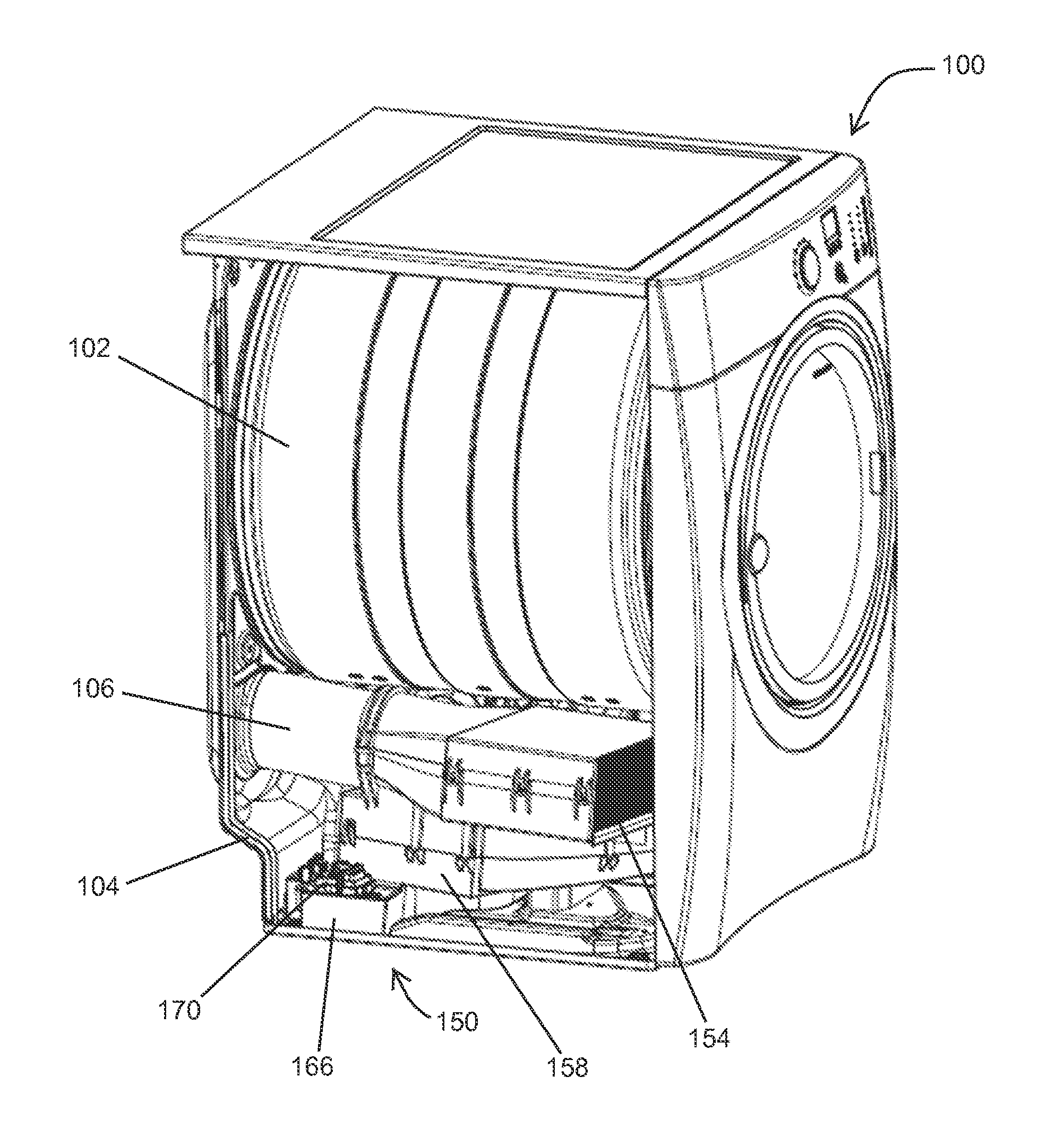
[0095]FIGS. 4-13 illustrate a first exemplary embodiment of vented tumble dryer 100 provided with a heat pump subassembly 150. The dryer 100 comprises a cabinet 104 with side walls, a top wall, and a bottom basement frame. The dryer 100 further comprises a rotating drum 102, process air fan 108, and heater tube 106 which may comprise multiple heating elements. The dryer 100 also includes, in a conventional fashion, a lint filter 112 (FIGS. 5-10) provided between the drum 102 and the blower 108. The dryer 100 may also include other elements traditionally known in a vented dryer (e.g., motor 116 in FIGS. 5-8).

[0096]As seen in, e.g., FIG. 7, the heat pump subassembly 150 of the laundry dryer 100 includes a compressor 152, condenser heat exchanger 154, expansion device 156, evaporator heat exchanger 158, and refrigerant tubing / conduits 160. The condenser and evaporator heat exchangers 154 and 158 thermally couple two circuits: a closed loop refrigerant circuit and an open or vented air ...


PUM


Abstract

A vented tumble laundry dryer is provided with a heat pump subassembly configured to join with a heater inlet and a blower outlet in an open air flow circuit. The heat pump subassembly forms a closed refrigerant loop. Condenser and evaporator heat exchangers of the subassembly form parts of the open air flow circuit. Air drawn from inside the dryer cabinet passes sequentially through the condenser heat exchanger, the heater, the dryer drum, the process air fan, and the evaporator heat exchanger before being vented to the outside. The heat exchangers have a modular construction that permits one to be stacked on the other and to be angularly offset with respect to the other in both horizontal and vertical planes, thus facilitating integration of the heat pump subassembly into existing vented dryer designs.

Description

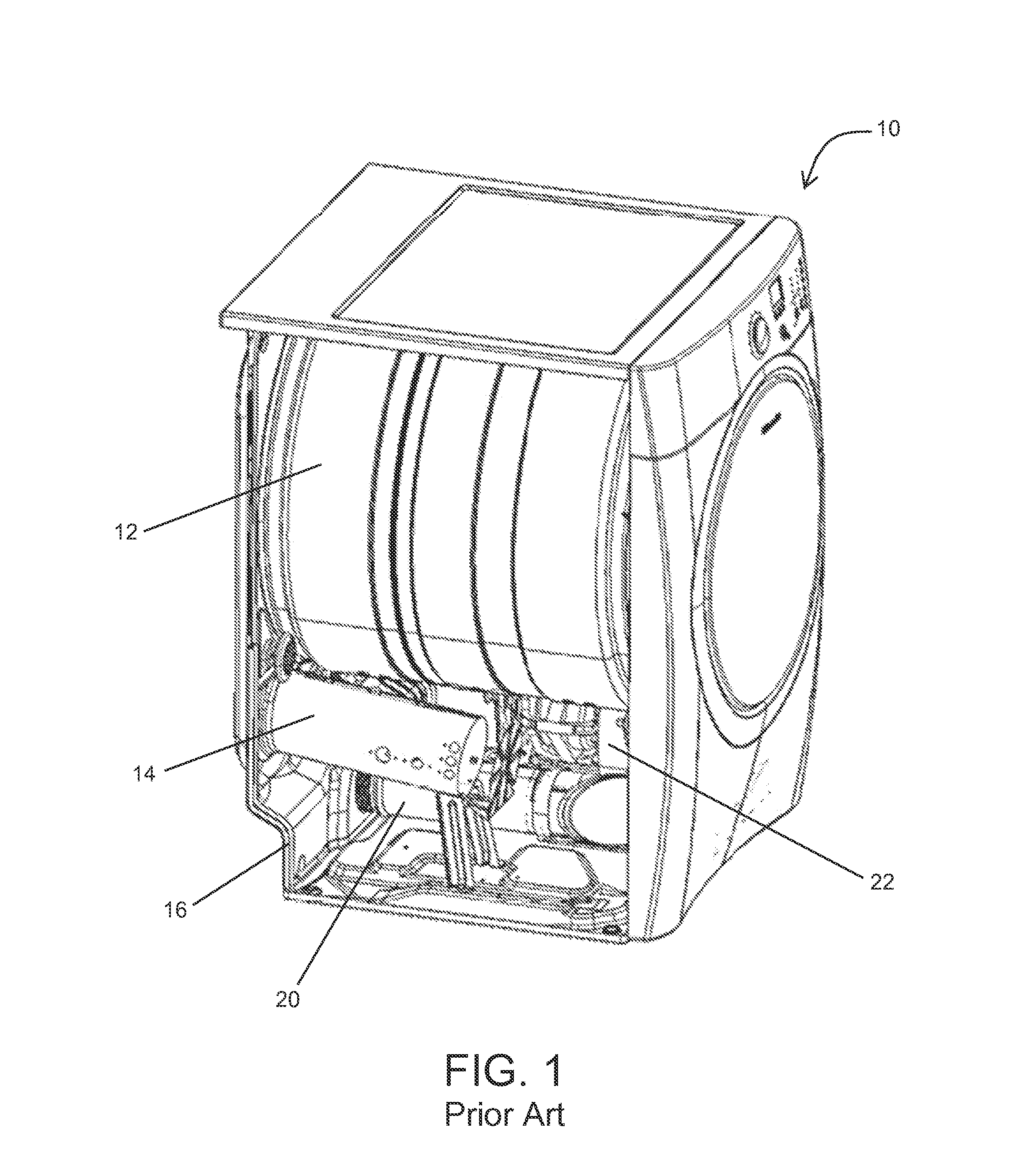
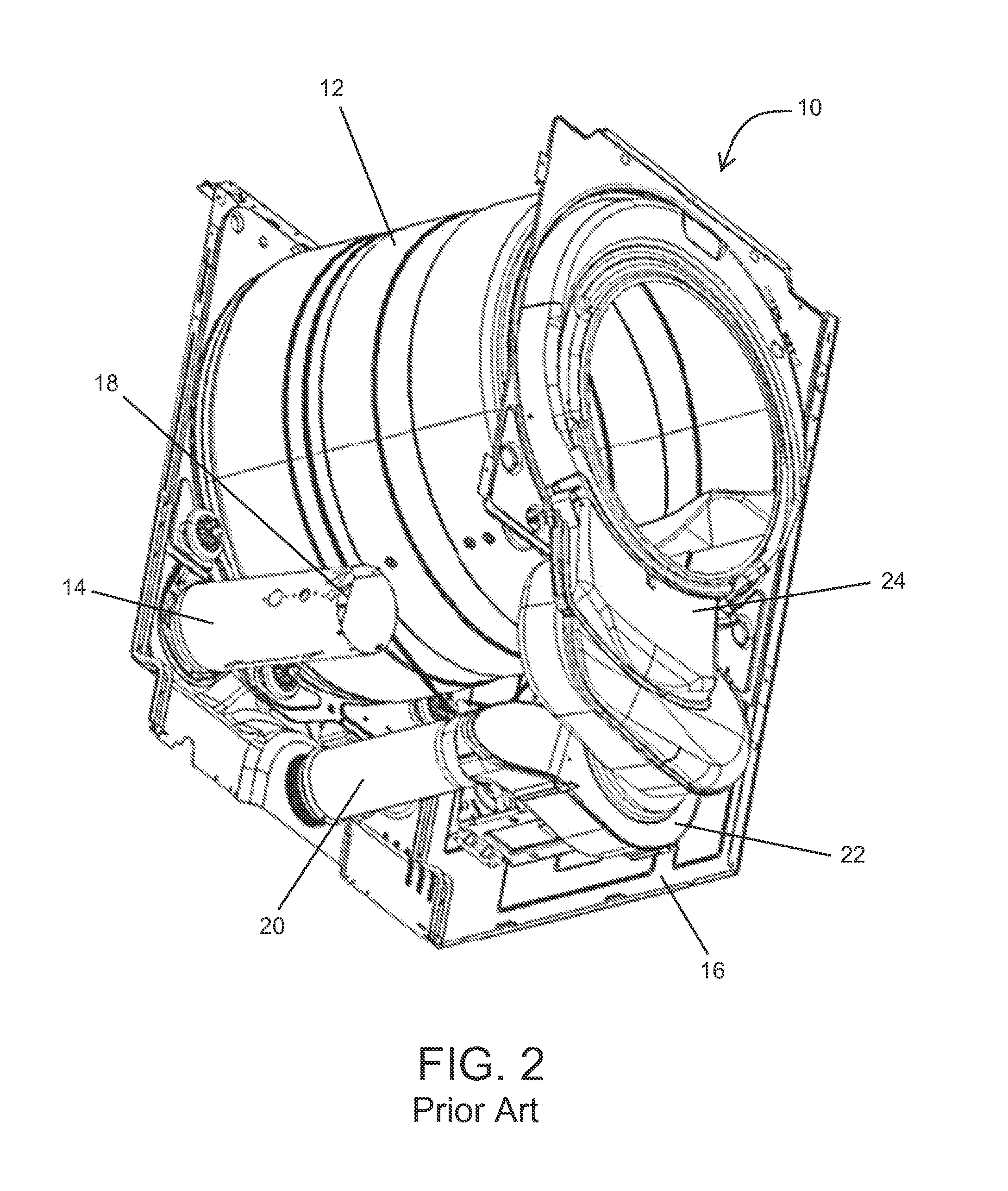
FIELD OF THE INVENTION[0001]The present invention relates generally to laundry dryers. In particular, the invention concerns a vented laundry dryer with a heat pump subassembly.BACKGROUND OF THE INVENTION[0002]Energy efficiency is an important aspect of a dryer, and improved heat recovery offers a valuable tool to improve overall energy efficiency. Conventionally, laundry dryers have existed as either a vented tumble dryer or a condenser dryer.[0003]During operation, a conventional vented tumble dryer draws air from the surrounding area, heats it, and directs it into the drum of the dryer. The dryer then exhausts the air and retained water vapor through a duct to the outside. As shown in FIGS. 1-3, a known vented dryer 10 generally includes a rotatable drum 12; an air supply duct 14 which introduces air from within the dryer housing or cabinet 16 into the drum 12; a heater 18 supplied at a heater tube portion of the air supply duct 14, which heats the air introduced into the air sup...

Claims


Application Information

Patent Timeline
IPC IPC(8): D06F58/20F25B30/02D06F58/24
CPCD06F58/206F25B30/02D06F58/24D06F58/20F28D1/0477
Inventor BISON, ALBERTOCAVARRETTA, FRANCESCOMISSIO, GABRIELESARTOR, LUCIANOSUSSARELLO, FEDERICOVIGNOCCHI, MASSIMILIANO
Owner ELECTROLUX APPLIANCES
Learn More