Release liner/layer, system and method of using the same with additive manufacturing

a technology of release liner and release liner, applied in the direction of manufacturing tools, rigid containers, transportation and packaging, etc., can solve the problems of reducing the efficiency of production, and requiring substantial driving force, so as to reduce or eliminate creases and/or corners, easy to remove and replace, and reduce the effect of cos

Inactive Publication Date: 2016-06-23
FULL SPECTRUM LASER
View PDF4 Cites 18 Cited by
  • Summary
  • Abstract
  • Description
  • Claims
  • Application Information

AI Technical Summary

Benefits of technology

[0016]In some embodiments, the vat provides a flexible, resilient release liner. The portion of the flexible, resilient release liner in contact with a formed lamina is able to flex during the additive manufacturing process and thus peels away from a formed lamina and returns to its pre-flex position during additive manufacturing. In some embodiments, the release liner is mounted to, or adjacent to, a support wall or plate, and in bottom-up stereolithography, for example, the support plate, in conjunction with the weight of the resin fluid in the vat, forces the release liner to lay flat against the support plate. In some embodiments, the plate is optically clear and, in conjunction with the release liner, provides an optically clear planar build plane. In some embodiments, the release liner can be readily removed and replaced.
[0017]The vat can be formed in a wide variety of ways. In certain embodiments, the vat may be formed by bending a sheet of flexible material or by thermoforming a material. In another embodiment, vats are formed from a sheet of flexible, resilient material bent to form retaining walls extending from a flexible, resilient release liner. In other embodiments, the resulting vat is deformable and leakproof during the additive manufacturing process and in some applications, some or all sheet bending reduces or eliminates creases and / or corners that may crack or leak. Further, bending of a flexible sheet to form all or part of a vat is easier and less costly than welding and / or gluing separate pieces together and molding or casting a leakproof one-piece container. In addition, it can be difficult to mold or cast large, thin, optically clear and sufficiently flat surfaces such as are often required for additive manufacturing.
[0018]As described herein, the release liner may have varying desired optical properties provided by differing surface treatments. In some instances, varying the surface treatment provides lower-cost laser beam shaping. In some embodiments, one side of the release liner is transparent and the other side is translucent.

Problems solved by technology

On the other hand, a long-known problem with bottom-up stereolithography is the adherence of the formed layers to the container surface supporting the layer as the layer is formed.
Separation of the formed layer from the container surface can require substantial driving force or relatively complex structure and methods of operation.
PDMS is soft and can be damaged relatively quickly by the stereolithography process due to micro-tearing of the surface as formed layers separate from the PDMS release layer.
The micro-tears cause the optical clarity of the PDMS layer to gradually degrade.
The loss of optical clarity in turn reduces the power and precision of the transmitted light beam that cures the build material therethrough.
As a result, the PDMS layer must be replaced resulting in an especially short service life.
FEP tends to be more resistant to damage than PDMS, but FEP does not release as well due to its higher level of adherence to formed layers.
FEP is also difficult to manufacture since typical adhesives do not adhere well to FEP.
Both PDMS and FEP are also relatively costly.
In addition, coating surfaces with PDMS or FEP is difficult and time consuming.
This is because: (i) many PDMS formulations present a respiratory hazard during mixing and curing and must be (a) applied to the vat surface in a dust free and temperature-regulated environment and (b) placed on an extremely level surface during curing for 12-48 hours or even longer; and (ii) FEP has very high non-stick properties similar to polytetrafluoroethylene (PTFE), and so FEP does not bond easily to the surface being coated, such as a vat or other build fluid container.
Another long-known problem with bottom-up stereolithography arises from the formed layer abutting the release layer while being immersed in a bath of unhardened resin fluid.
The additional mechanical and other components required to accomplish such peeling or sliding increase the cost of the printer and the points of possible failure in the printer.
In addition, it can be difficult to mold or cast large, thin, optically clear and sufficiently flat surfaces such as are often required for additive manufacturing.

Method used


Image

  • Release liner/layer, system and method of using the same with additive manufacturing
  • Release liner/layer, system and method of using the same with additive manufacturing
  • Release liner/layer, system and method of using the same with additive manufacturing

Examples


Embodiment Construction

[0035]For the purposes of promoting an understanding of the principles in accordance with the embodiments of the present invention, reference will now be made to the embodiments illustrated in the drawings and specific language will be used to describe the same. It will nevertheless be understood that no limitation of the scope of the invention is thereby intended. Any alterations and further modifications of the inventive feature illustrated herein, and any additional applications of the principles of the invention as illustrated herein, which would normally occur to one skilled in the relevant art and having possession of this disclosure, are to be considered within the scope of the invention claimed.

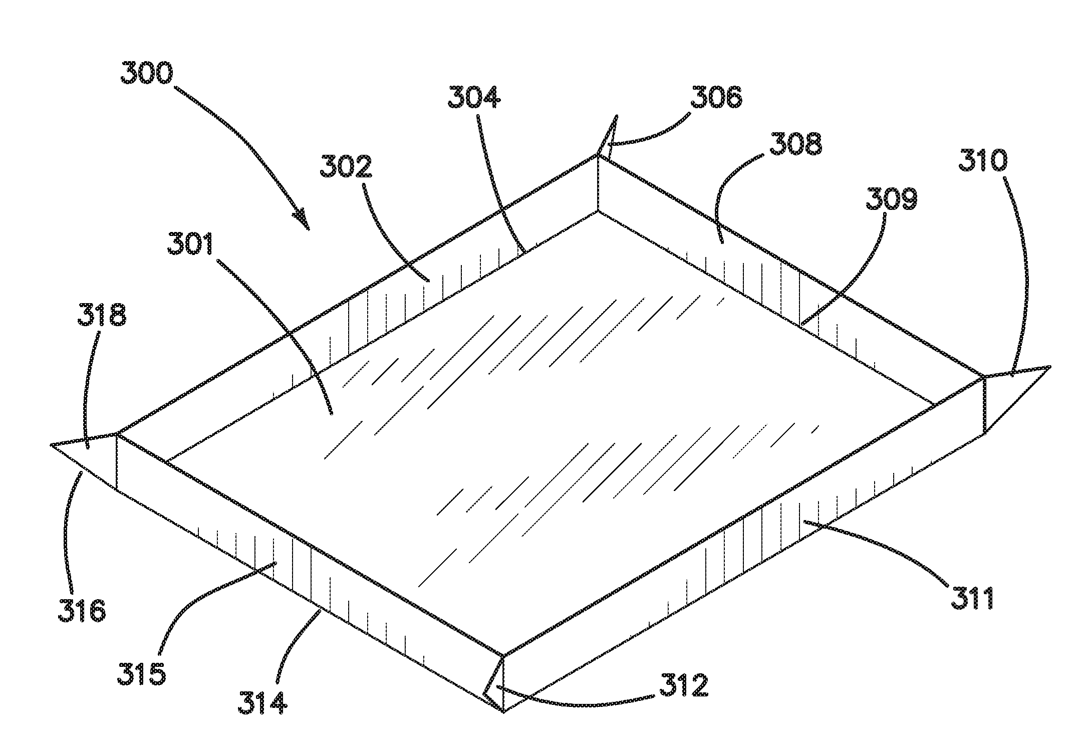
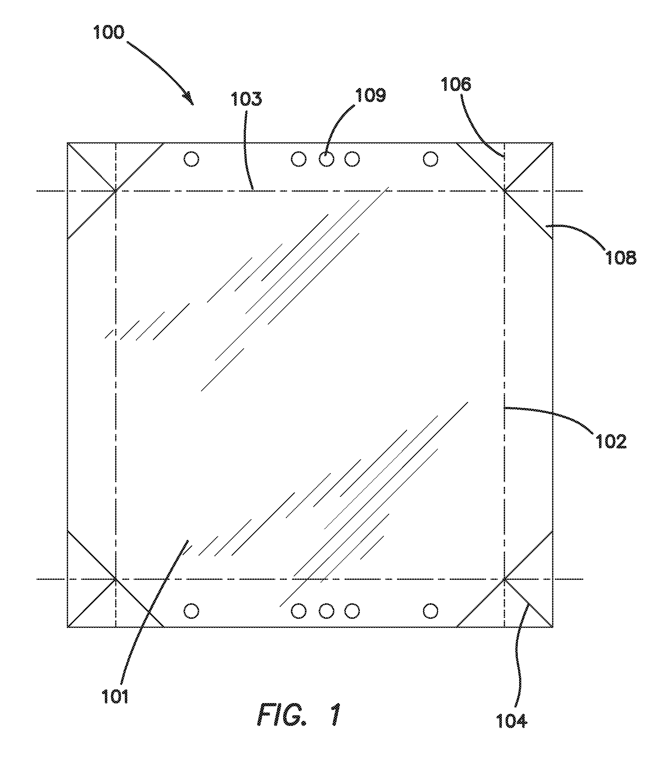
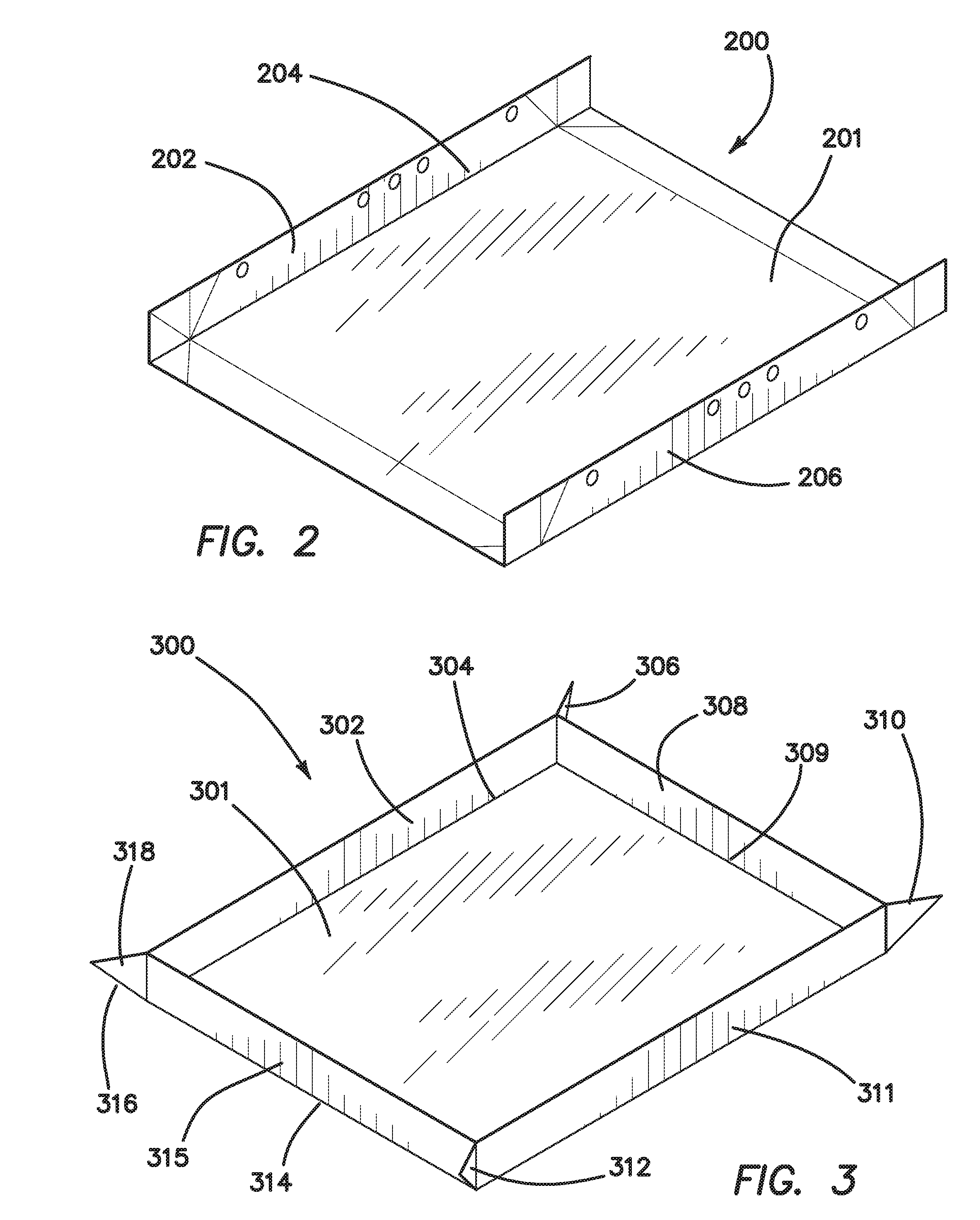
[0036]With reference to FIG. 1, a generally planar resilient sheet 101 is formable into a resin fluid vat (not shown in FIG. 1—see resin fluid vat 314 in FIG. 4). In the embodiment of FIG. 1, the resilient sheet 101 is deformable along a planned layout or pattern of bend lines (e.g., ...


PUM

PropertyMeasurementUnit
thickaaaaaaaaaa
thicknessaaaaaaaaaa
thicknessaaaaaaaaaa

Abstract

Release liner forming structures and methods of making and using the same. The methods of making the release liner include thermoforming and sheet bending. The flexible release liner may be used in conjunction with a rigid, transparent supporting surface. The release liner may be developed from a flexible sheet formed into a deformable resin fluid vat. A release layer, and additional structure if desired, can be formed of or include plastic, such as polyolefin or fluoropolymer. In some instances, the polyolefin is, or includes, polymethylpentene or a fluropolymer is fluorinated ethylene propylene. The optical and other properties of the release layer can be altered with treatments and other materials to, for example, reduce over-penetration of a light beam or deform a release layer.

Description

CROSS-REFERENCE[0001]This application claims priority to U.S. Patent Application No. 62 / 069,389 filed Oct. 28, 2014 which is incorporated herein for any and all purposes.FIELD OF THE INVENTION[0002]The embodiments of the present invention relate to release liner technologies for additive manufacturing.BACKGROUND OF THE INVENTION[0003]Additive manufacturing, also known as 3D printing, is a term describing a variety of manufacturing technologies in which an object is printed / created from a 3D model through selective accumulation of material. Most additive manufacturing methods create three dimensional objects through sequential construction of thin layers or slices that have edges approximating the object's boundary surfaces. Additive manufacturing technologies include fused deposition modeling (FDM), layered inkjet deposition, selective laser sintering (SLS) and stereolithography.[0004]Stereolithography can be built in a top-down or bottom-up fashion. With the top-down approach, a li...

Claims


Application Information

Patent Timeline
Patent Type & Authority Applications(United States)
IPC IPC(8): B29C67/00B65D5/56B65D5/28B65D5/42B65D5/20
CPCB29C67/0085B29C67/0066B65D5/4279B65D5/20B29K2883/00B65D5/209B65D5/563B33Y30/00B29K2827/18B65D5/28B29C53/04B65D2301/20B33Y10/00B29C64/135B29C64/245
Inventor LIU, HENRY
Owner FULL SPECTRUM LASER
Why Eureka
Try Eureka