
Air conditioning device for vehicle

a technology for air conditioning devices and vehicles, which is applied in the direction of heat pumps, domestic cooling devices, batteries, etc., can solve the problems of possible degraded heating performance, and achieve the effect of improving heating performance and increasing the density of refrigerant drawn into the compressor

Active Publication Date: 2016-06-23
DENSO CORP
View PDF22 Cites 13 Cited by
  • Summary
  • Abstract
  • Description
  • Claims
  • Application Information

AI Technical Summary

Benefits of technology

The present disclosure is about an air conditioning device for a vehicle that can improve heating performance at a low outside air temperature. The device uses two low-pressure side heat exchangers to exchange heat between the refrigerant and the heating medium other than the air. This results in a higher refrigerant temperature even at low outside air temperatures, which improves heating performance. In addition, the device allows for better absorption of heat from the air and waste heat of in-vehicle devices. The heat quantity of the heating medium that is heated in the high-pressure side heat exchanger can be introduced to the first low-pressure side heat exchanger, which increases the density of the refrigerant and improves heating performance even at low outside air temperatures. Overall, the patent provides a solution to improve heating performance at low outside air temperatures through efficient heat exchange and improved refrigerant density.

Problems solved by technology

As a result, heating performance is possibly degraded.

Method used


Image

  • Air conditioning device for vehicle
  • Air conditioning device for vehicle
  • Air conditioning device for vehicle

Examples


Embodiment Construction

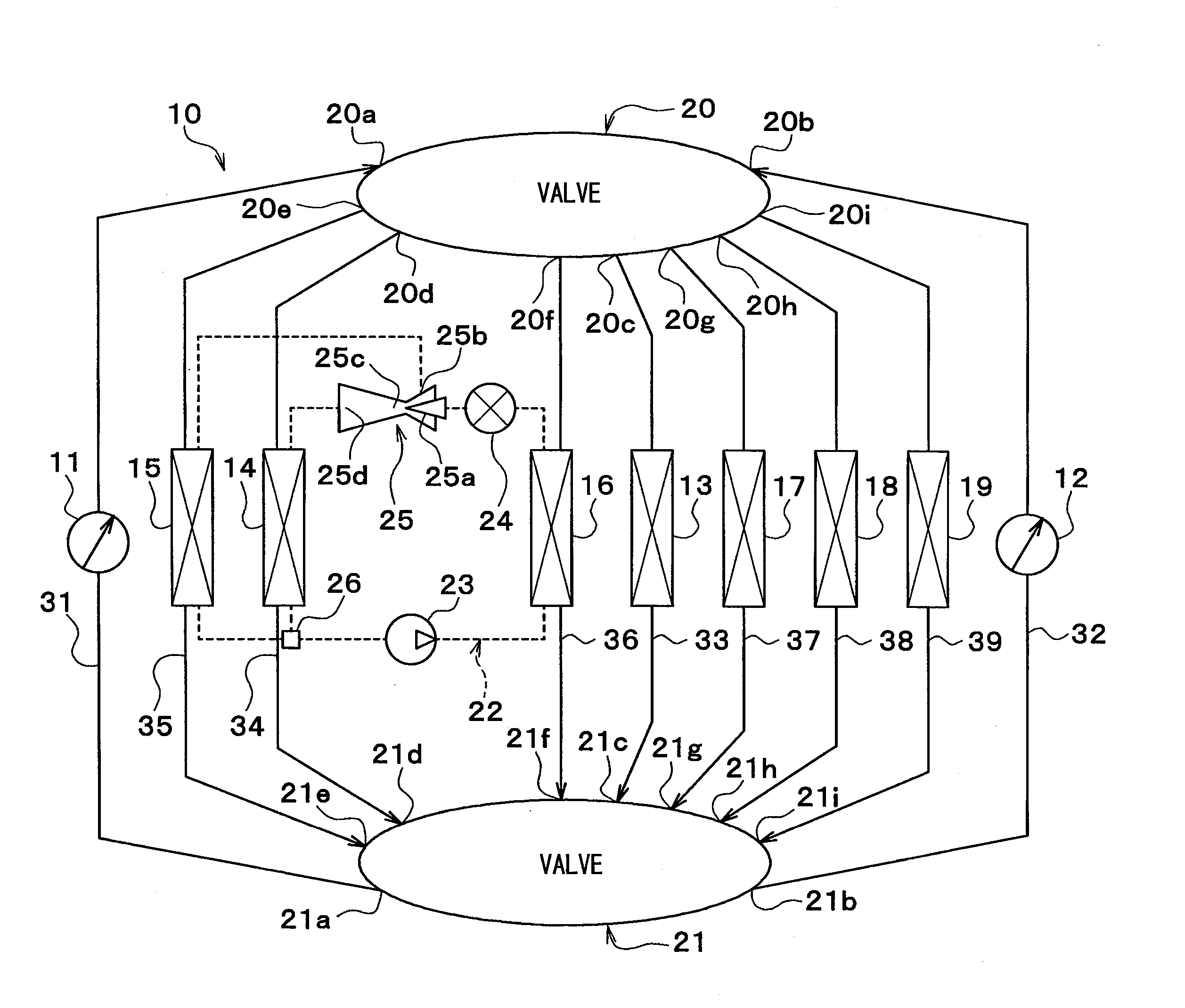
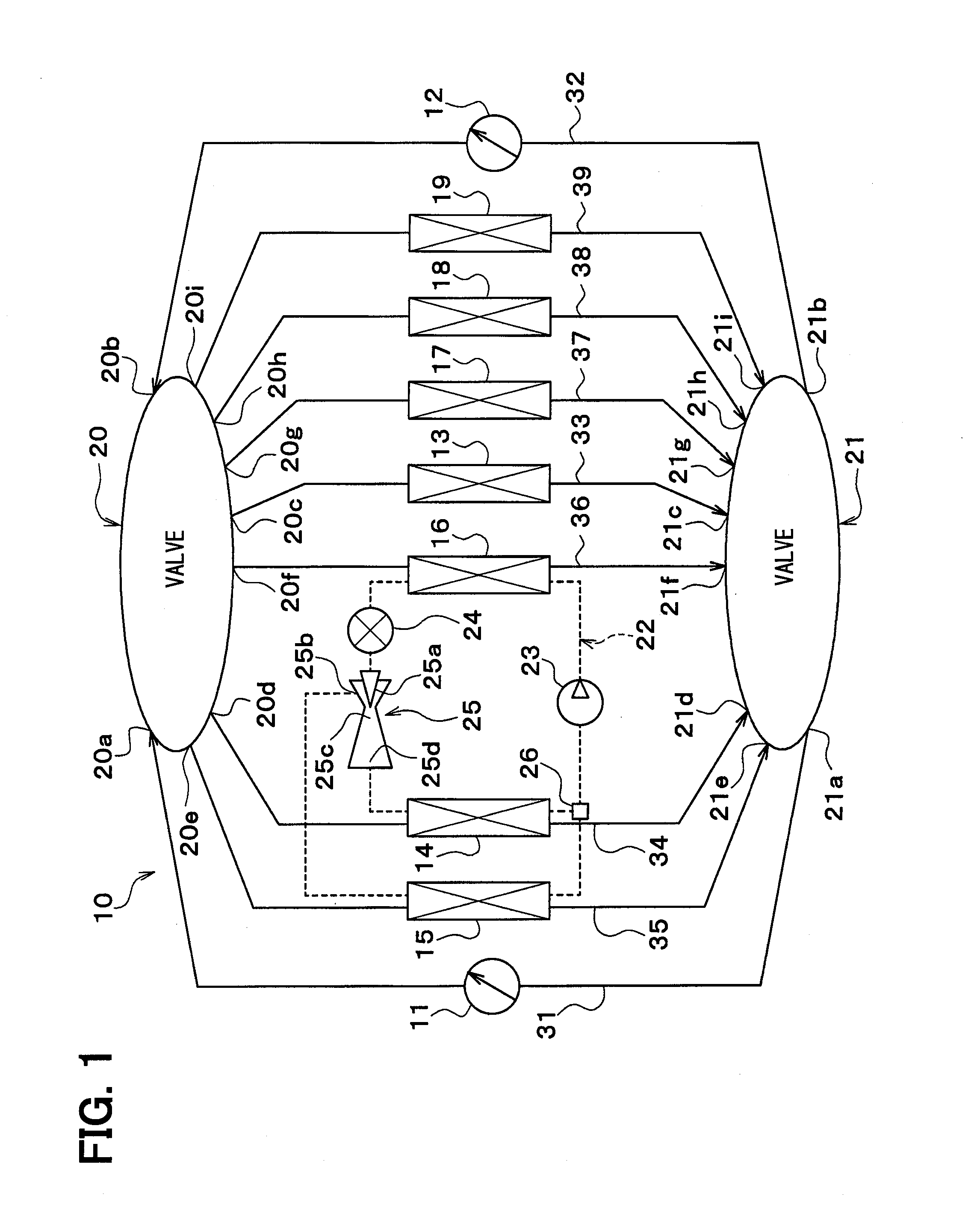
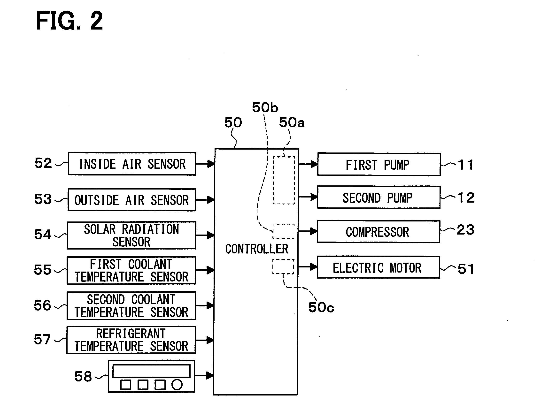
[0024]A description will hereinafter be made on an embodiment on the basis of FIG. 1 to FIG. 6. A vehicular heat management system 10 shown in FIG. 1 is used to adjust various types of device provided in a vehicle and inside of a vehicle cabin at an appropriate temperature. In this embodiment, the vehicular heat management system 10 is applied to a hybrid vehicle that obtains drive power for a vehicle travel from an engine (i.e., an internal combustion engine) and an electric motor for travel.

[0025]The hybrid vehicle of this embodiment is a plug-in hybrid vehicle that can store electric power supplied from an external power source (i.e., a commercial power source) during parking of the vehicle in a battery mounted in the vehicle (i.e., an in-vehicle battery). A lithium-ion battery can be used as the battery, for example.

[0026]The drive power output from the engine is used not only for the vehicle travel but is also used to actuate a generator. The electric power generated by the gen...


PUM

PropertyMeasurementUnit
temperatureaaaaaaaaaa
aspect ratioaaaaaaaaaa
pressureaaaaaaaaaa

Abstract

An air conditioning device for a vehicle has a compressor that supplies a high-pressure refrigerant by drawing and discharging a refrigerant, an air heating heat exchanger heating air that is to be blown into a vehicle cabin by using heat of the high-pressure refrigerant, a pressure reduction part expanding and decompressing the high-pressure refrigerant and supplying as an intermediate-pressure refrigerant and a low-pressure refrigerant, a first low-pressure side heat exchanger exchanging heat between the intermediate-pressure refrigerant and a heating medium other than the air, a second low-pressure side heat exchanger cooling the heating medium by exchanging heat between the low-pressure refrigerant and the heating medium, a first heating medium circuit through which the heating medium cooled in the second low-pressure side heat exchanger circulates, and a heating medium-air heat exchanger causing the heating medium to absorb heat by exchanging heat between the air and the heating medium circulating through the first heating medium circuit. The heating medium heated in the high-pressure side heat exchanger is capable of being introduced to the first low-pressure side heat exchanger.

Description

CROSS REFERENCE TO RELATED APPLICATION[0001]This application is based on Japanese Patent Application No. 2013-158656 filed on Jul. 31, 2013, the disclosure of which is incorporated herein by reference.TECHNICAL FIELD[0002]The present disclosure relates to an air conditioning device for a vehicle.BACKGROUND ART[0003]As described in Patent Literature 1, an air conditioning device for a vehicle is conventionally known to have an exterior heat exchanger and an interior condenser. In the exterior heat exchanger, an outside air exchanges heat with a low-pressure side refrigerant of a refrigeration cycle. In the interior condenser, a high-pressure side refrigerant of the refrigeration cycle exchanges heat with air that is to be blown into a vehicle cabin.[0004]In this conventional art, the low-pressure side refrigerant of the refrigeration cycle absorbs heat from the outside air in the exterior heat exchanger, and the high-pressure side refrigerant in the refrigeration cycle radiates heat ...

Claims


Application Information

Patent Timeline
Patent Type & Authority Applications(United States)
IPC IPC(8): F25B25/00H01M10/625H01M10/663F25B30/02F25B49/02
CPCF25B25/005F25B30/02H01M2220/20H01M10/663H01M10/625F25B49/02B60H1/00899B60H2001/3298F25B41/00F25B2341/0011F25B2339/047B60H1/00278B60H2001/00307G10L2019/0014B60H1/32284Y02E60/10
Inventor KATOH, YOSHIKIMAKIHARA, MASAMICHIKUWAYAMA, KAZUTOSHIENOMOTO, NORIHIKOSUGIMURA, KENGO
Owner DENSO CORP
Learn More