
Dual catheter ablation system

a catheter and ablation system technology, applied in the field of medical devices, can solve the problems of limiting the effectiveness of this approach, increasing the likelihood of damaging the renal arterial wall, dissection, stenosis or thrombosis, etc., and achieves the effect of greatly enhancing the likelihood of successful ablation and greatly reducing the distance between the ablation element and the target tissu

Inactive Publication Date: 2016-06-30
KRISHNAN SUBRAMANIAM C
View PDF3 Cites 21 Cited by
  • Summary
  • Abstract
  • Description
  • Claims
  • Application Information

AI Technical Summary

Benefits of technology

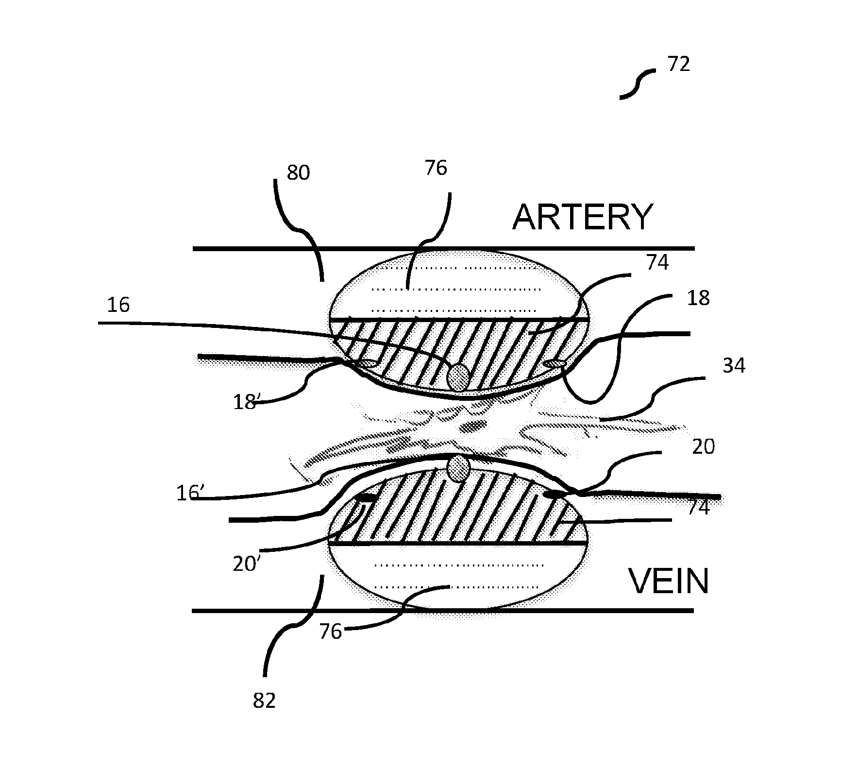
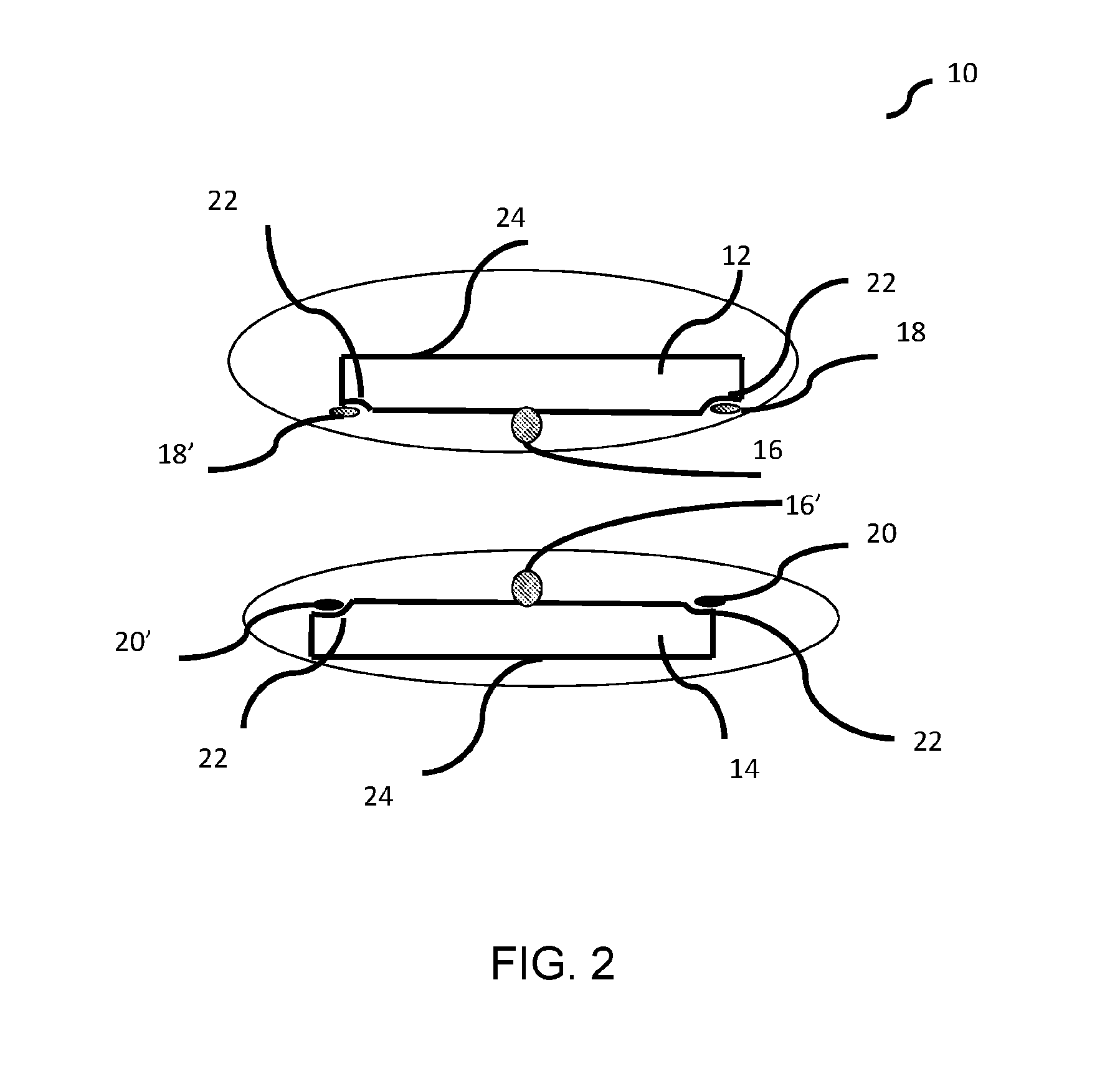
The patent text describes a dual catheter ablation system that can effectively kill target tissue. The system includes an arterial catheter and avenous catheter, each with an electrode that can be used to ablate tissue. The system also includes magnetic elements that are placed near the electrodes. A protective sheath may be used to enclose the catheters and magnetic elements. The system can be placed inside the body to target specific tissue between the electrodes or between the magnetic elements. The technical effect is a more effective way to ablate tissue using a dual catheter system.

Problems solved by technology

Nerve structures further away are less likely to be affected, thus limiting the effectiveness of this approach.
To ablate structures not in direct contact with the vessel wall, higher power will be needed and this could increase the likelihood of damaging the renal arterial wall, causing dissection, stenosis or thrombosis.
Prior experience in procedures of the heart has shown that attempts to ablate the entire thickness of the target tissue in the atrium or ventricle with conventional unipolar ablation techniques is very difficult to achieve.
One of the main problems with this approach is the development of “collateral” damage i.e. damage to the neighboring structures such as the esophagus, phrenic nerves etc.
Likely due to the technical difficulties, the success rates of catheter ablation for conditions such as persistent atrial fibrillation is poor.

Method used


Image

  • Dual catheter ablation system
  • Dual catheter ablation system
  • Dual catheter ablation system

Examples


Embodiment Construction

[0024]As used herein and in the claims, the singular forms “a,”“an,” and “the” include the plural reference unless the context clearly indicates otherwise.

[0025]With radiofrequency ablation, to overcome the disadvantages of the unipolar approach as described hereinabove, a bipolar approach where there are two catheters across the wall of the target tissue is considered more successful in creating transmural necrosis since an ablation lesion will develop adjacent to both catheter electrodes. In this technique, energy is delivered between two electrodes. This potentially results in a more focused delivery of energy which could also minimize lesion width and collateral tissue injury.

[0026]Unlike unipolar RF where a skin patch functions as an indifferent electrode (and therefore lesion develops adjacent only to the active electrode), here both electrodes function as active electrodes. Hence, lesions due to coagulation necrosis develop adjacent to both electrodes. A bipolar approach with...


PUM


Abstract

A dual catheter ablation system with an arterial catheter and a venous catheter and at least two magnetic elements, a first magnetic element placed in the arterial catheter and a second magnetic element placed in the venous catheter, where at least one of the arterial catheter or the venous catheter carries an ablating electrode. The first magnetic element has a predefined polarity and the second magnetic element has an opposite polarity with respect to the pre-defined polarity. A protective sheath is provided for enclosing the catheter pair, the first magnetic element and the second magnetic element. The dual catheter ablation system is configured to be placed inside an anatomical region such that a target tissue is in between the first magnetic element and the second magnetic element, bringing the ablating electrode in close proximity to a target tissue.

Description

CROSS-REFERENCE TO RELATED APPLICATIONS[0001]This application is a continuation of PCT International Appl. No. PCT / IB2014 / 064596 filed Sep. 17, 2014, which claims benefit of priority to U.S. Provisional Patent Appl. No. 61 / 879,036, filed on Sep. 17, 2013, the content of each of which is incorporated herein by reference in its entirety.FIELD OF THE INVENTION AND USE OF INVENTION[0002]The invention relates generally to medical devices and more specifically to a catheter system for percutaneous ablation of perivascular tissues, useful for cardiovascular procedures.PRIOR ART AND PROBLEM TO BE SOLVED[0003]Renal sympathetic denervation (RSDN), also referred as renal denervation (RDN), is a minimally invasive, endovascular catheter based procedure using ablation for treating resistant hypertension (high blood pressure). In this procedure, radiofrequency (RF) or other energy pulses are applied to the wall of the renal arteries using a catheter, and the nerves in the vascular wall are denude...

Claims


Application Information

Patent Timeline
Patent Type & Authority Applications(United States)
IPC IPC(8): A61B18/14A61M25/10A61B18/04A61B18/02A61B18/24A61B18/18
CPCA61B18/1492A61B18/24A61B18/1815A61B18/04A61B18/02A61B18/18A61B2018/00505A61B2018/046A61B2018/048A61B2018/0212A61B2018/00577A61B2017/00778A61M25/10A61B18/1442A61B2018/00279A61B2018/00351A61B2018/00404A61B2018/00285
Inventor KRISHNAN, SUBRAMANIAM C.
Owner KRISHNAN SUBRAMANIAM C
Learn More