
Method and apparatus for recycling top gas for shaft furnace

a top gas and shaft furnace technology, applied in lighting and heating equipment, furnaces, manufacturing converters, etc., can solve the problems of high ash and sulfur content of lump ore and coal, low efficiency, and high energy and capital costs of processes, so as to reduce adverse environmental impact and improve energy efficiency

Active Publication Date: 2016-06-30
GAS TECH INST
View PDF1 Cites 7 Cited by
  • Summary
  • Abstract
  • Description
  • Claims
  • Application Information

AI Technical Summary

Benefits of technology

The present invention describes a way to make iron using a direct reduction iron production process. This method uses a portion of the top gas produced during the gasification process to transport the materials needed for iron production. This method results in improved energy efficiency and reduced harmful environmental impact.

Problems solved by technology

Rotary kiln production is limited because the kiln cannot be built larger than about 200,000 tons per year.
Also, the use of lump ore and coal with high levels of ash and sulfur yields in low quality product.
These processes all have high energy and capital costs and low efficiency.
The syngas exiting the gasifier is hot, dirty, and contains a significant amount of non-reducing gas components.

Method used


Image

  • Method and apparatus for recycling top gas for shaft furnace
  • Method and apparatus for recycling top gas for shaft furnace
  • Method and apparatus for recycling top gas for shaft furnace

Examples


example 1

Use of the Top Gas as Transport Gas Reduces Power Consumption

[0057]Table 1 below shows a comparison of energy consumption between using the shaft furnace (SF) top gas (TG) and CO2 as transport gas. By replacing CO2 with a portion of the top gas, the consumption of O2 at the gasifier was reduced from 1645 kgmol / h to 1604 kgmol / h. Because O2 is normally produced by an Air Separation Unit (ASU), less consumption of O2 resulted in less power consumption (from 26797 kW to 26129 kW) at the ASU, provided that the power consumption at the ASU per unit O2 remains 16.29 kW / kgmol. Furthermore, the volume of syngas required to produce DRI was decreased from 800 Nm3 / ton to 700 Nm3 / ton while the DRI production was increased from 142 ton / h to 144 ton / h. Less syngas required to produce DRI further contributed to less coal per ton of direct reduced iron. These results show that less power per ton of direct reduced iron is used by using the top gas as transport gas.

TABLE 1Comparison of Power Consumpt...

example 2

TG Volume to be Recycled was Reduced if Top Gas was Used as Fuel

[0059]Table 3 shows a comparative example illustrating that when a portion of the top gas was used as transport gas for the gasifier, the volume of top gas recycled as reduction gas was further decreased. Results here showed that the needed capacity of the DRI CO2 removal system was reduced by 20%, further reducing energy consumption of the system.

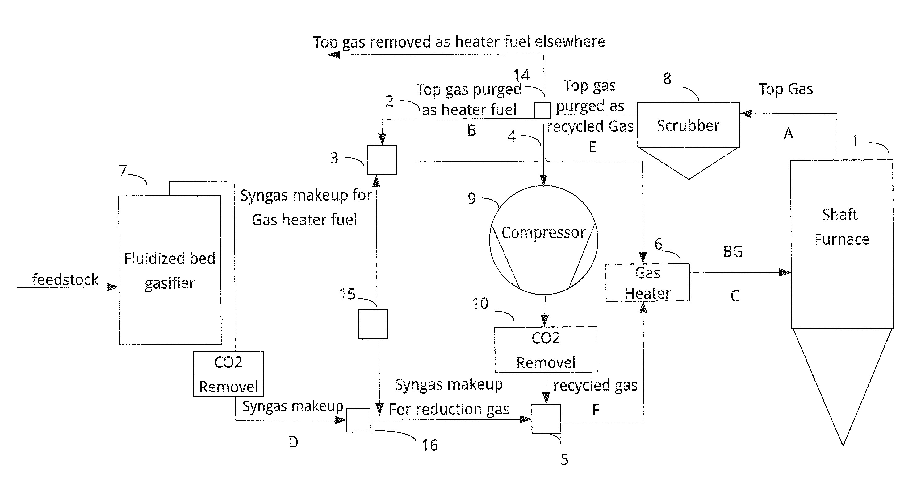
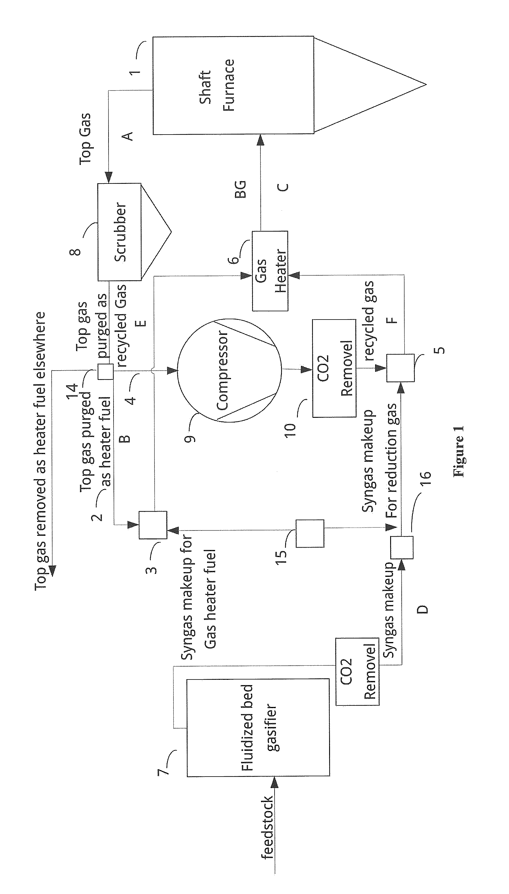
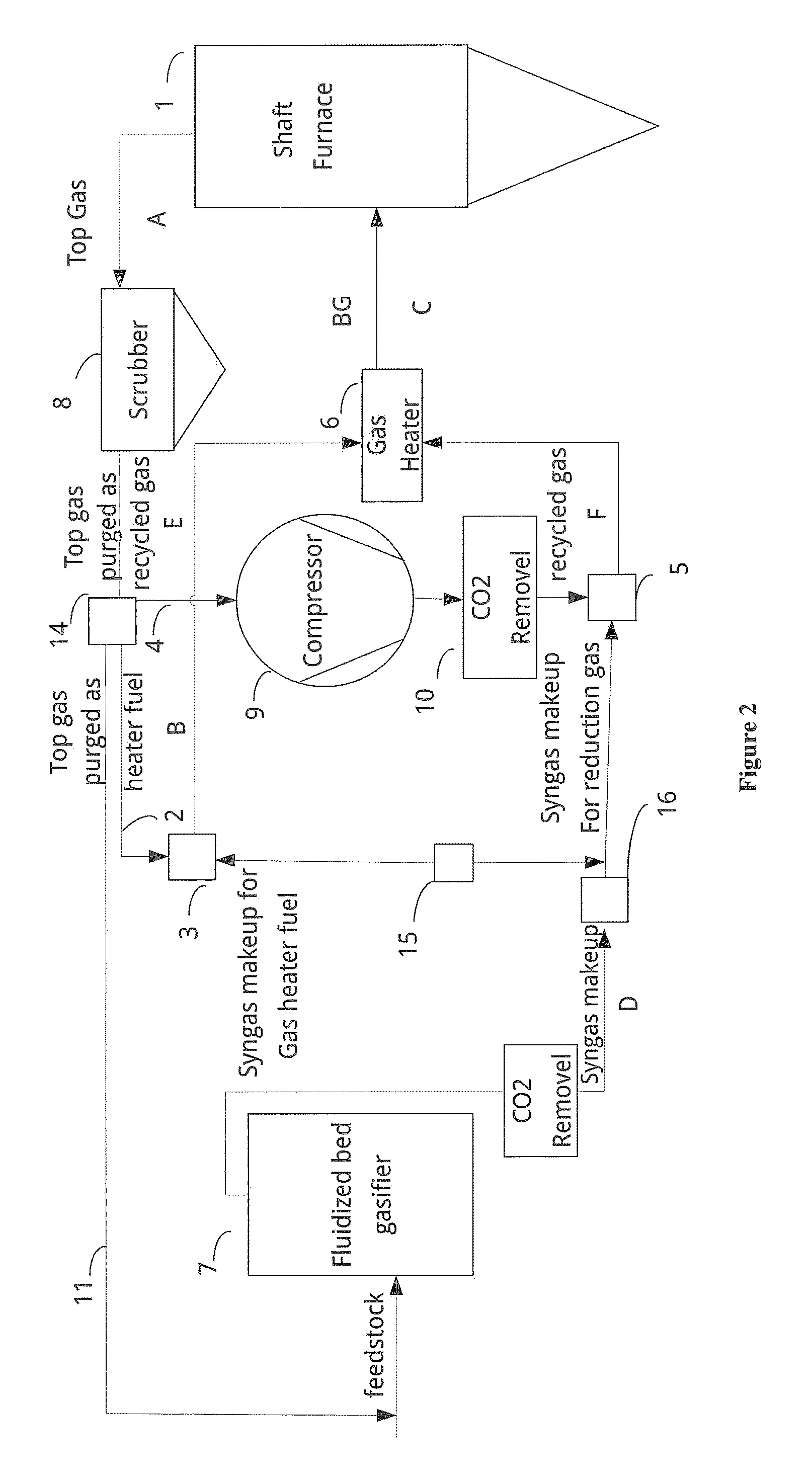
[0060]As shown in FIG. 1, top gas can be used as gas heater fuel without sending it back to the gasifier. By contrast, as in FIG. 2, the top gas is used as gas heater fuel as well as transport gas for the gasifier. The gas volumes at positions A, B, C, D, E and F in FIGS. 1 and 2 are shown in Table 3.

TABLE 3Comparison of Gas Volumes in FIG. 1 and FIG. 2PositionBDEFASF TGCSyngasRecycledRecycledSF TGpurgedBGMakeupgasgasFIG. 1196,92731,885 184,876 88,329123,360101,117(Nm3 / h)FIG. 2199,53061,199*186,738108,500 96,375 77,572(Nm3 / h)%—91% more——20% less23% less*This amount includes th...

example 3

Use of Top Gas as Transport Gas Increased Overall System Energy Efficiency, and Net Syngas Output Per Unit Coal, and Reduces O2 and Stem Consumption

[0063]FIG. 3 shows the overall arrangement of two exemplary gasifier systems, with the same coal consumption. In one, only CO2 was used as transport gas, while in the other, a portion of the shaft furnace gas was used as part of transport gas. In both cases, the syngas from the gasifier was cleaned through an AGR unit, and then mixed with the recycled top gas. As shown in Table 5, when a portion of the shaft furnace gas was used as part of the transport gas, a net volume increase in H2+CO+CH4 (1,830 Nm3 / h) was achieved while the consumption of oxidant and steam was respectively decreased by 1,311 kg / h and 11,323 kg / h.

TABLE 5Comparisons of Gasifier PerformanceRaw SyngasTransport GasOxidantHP SteamOutput Gas(H2 + CO + CH4)CO2 asCO252,636 kg / h71,420 kg / h266,687 kg / h113,334 Nm3 / hTransport Gas42.909 kg / hSF RG asCO251,325 kg / h60,097 kg / h234,52...


PUM

PropertyMeasurementUnit
temperatureaaaaaaaaaa
poweraaaaaaaaaa
poweraaaaaaaaaa

Abstract

Method, apparatus and system for improved energy efficiency in a direct reduction iron production process which uses a direct reduction shaft furnace and syngas as the reduction gas. The method and system of the invention use a part of the top gas emanating from the shaft furnace as transport gas for the gasifier, and control the volume of the top gas used as recycled top gas or fuel for the gas heater. The present invention achieves high energy efficiency, and reduces the need to use additional CH4 source for the reduction gas.

Description

FIELD OF THE INVENTION[0001]The present invention relates to direct reduction of iron ore. More specifically, the invention relates to a method and apparatus for minimizing the amount of top gas emanating from a direct reduction iron shaft furnace to be recycled back to the shaft furnace; and for using a portion of the purged top gas in a coal gasification process to lower overall power consumption, carbon emission, capital expenses, and operational expenses of direct reduction iron production.BACKGROUND OF THE INVENTION[0002]Direct reduction iron (DRI) production has been developed to overcome difficulties (e.g. high capital expense, high pollution, and the need of coking coal) of conventional blast furnaces. Direct reduction typically uses shaft furnaces (such as the MIDREX® Process) or coal-fired rotary kilns. Rotary kiln production is limited because the kiln cannot be built larger than about 200,000 tons per year. Also, the use of lump ore and coal with high levels of ash and s...

Claims


Application Information

Patent Timeline
Patent Type & Authority Applications(United States)
IPC IPC(8): C21B13/00F27D17/00F27B15/10C21B13/02F27B1/10
CPCC21B13/0033C21B13/008C21B13/02F27D17/004F27B15/10F27D17/001F27B1/10Y02P10/143Y02P10/122
Inventor WINTER, JOHN D.MICHISHITA, HARUYASU
Owner GAS TECH INST
Features
  • Generate Ideas
  • Intellectual Property
  • Life Sciences
  • Materials
  • Tech Scout
  • Unparalleled Data Quality
  • Higher Quality Content
  • 60% Fewer Hallucinations
Learn More