Ultra capacitor module

a technology of ultra-capacity and modules, applied in the direction of electrolytic capacitors, fixed connections, printed circuit non-printed electric components association, etc., can solve the problems of increasing production costs, increasing the number of product assembly operations, and increasing production costs, so as to reduce resistance, reduce production costs, and reduce production costs

Active Publication Date: 2016-06-30
LS MATERIALS CO LTD
View PDF2 Cites 4 Cited by
  • Summary
  • Abstract
  • Description
  • Claims
  • Application Information

AI Technical Summary

Benefits of technology

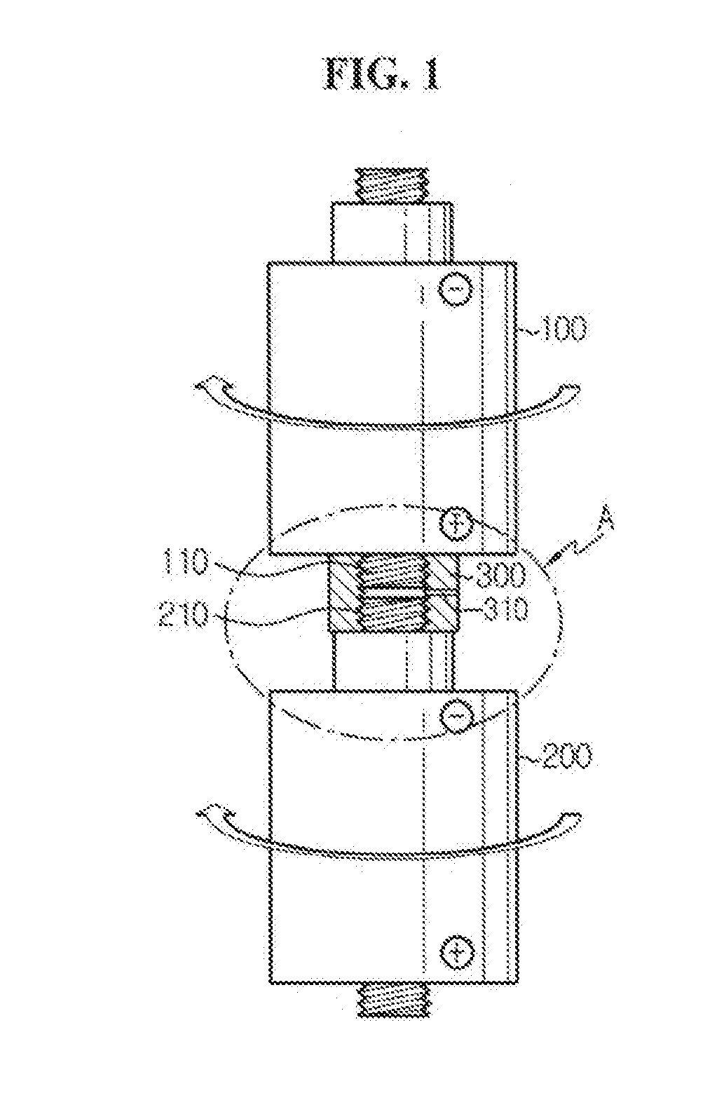
[0035]According to one aspect of the present disclosure, only a nut is used to connect ultra capacitors in series, and thus, when connecting a plurality of ultra capacitors, component saving results in curtailment of production costs and reduction in operation time.
[0036]Also, the resistance reduces and the heat transfer performance is improved, leading to longer product life.
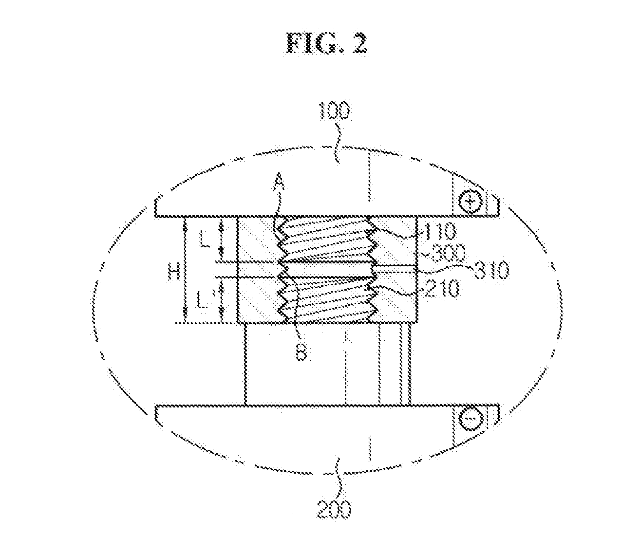
[0037]Also, gas generated during charging and discharging of ultra capacitors is emitted, thereby preventing an explosion.
[0038]According to another aspect of the present disclosure, there is no need for separate processing of a bolting part to connect a harness to a connecting member, resulting in reduced manufacturing costs of products.
[0039]Also, a member having an elastic property is provided under a printed circuit board (PCB) so that the PCB may rotate in contact with a connecting member, which makes it easy to set a connector in one direction, the connector to which a harness is to be connected.
[0040]According to still another aspect of the present disclosure, a PCB is fixed while being inserted into a terminal of a connector, so the need for a separate structure for fixing the PCB is eliminated.

Problems solved by technology

However, the foregoing-structured ultra capacity assembly needs a plurality of busbars and nuts to connect a plurality of ultra capacitors.
This ultra capacitor module has a drawback in that as the number of ultra capacitors connected in series increases, production costs rise and product assembly operations increase in number with the increasing number of components.
Also, since the entire connecting structure increases in resistance due to the presence of the contact resistance between the busbar and the ultra capacitor, there is a problem of a large amount of heat being generated.
Also, the high voltage ultra capacitor module made by connecting in series is susceptible to cell voltage imbalance during charge, standby or discharge due to a characteristic parameter difference.
Also, in some cases, a certain cell may break down or explode due to its overvoltage.
However, the above-mentioned configuration has a disadvantage in that production costs are subject to increase due to an additional process of forming the bolting part on the nut.
Also to ease the connection of the harness connecting the bolting part and the balancing board, the bolting part must run in a fixed direction: however, there is a drawback in that it is difficult to fix the bolting part in one direction.
Also, there is a disadvantage in that a separate structure is needed to fix the balancing board.

Method used


Image

  • Ultra capacitor module
  • Ultra capacitor module
  • Ultra capacitor module

Examples


Embodiment Construction

[0052]Hereinafter, preferred embodiments of the present disclosure will be described in detail with reference to the accompanying drawings. Prior to the description, it should be understood that the terms used in the specification and the appended claims should not be construed as limited to general and dictionary meanings, but interpreted based on the meanings and concepts corresponding to technical aspects of the present disclosure on the basis of the principle that the inventor is allowed to define terms appropriately for the best explanation. Therefore, the description proposed herein is just a preferable example for the purpose of illustrations only, not intended to limit the scope of the disclosure, so it should be understood that other equivalents and modifications could be made thereto without departing from the spirit and scope of the disclosure.

[0053]Also, in the description of the present disclosure, when it is deemed that specific explanation of related well-known constr...


PUM


Abstract

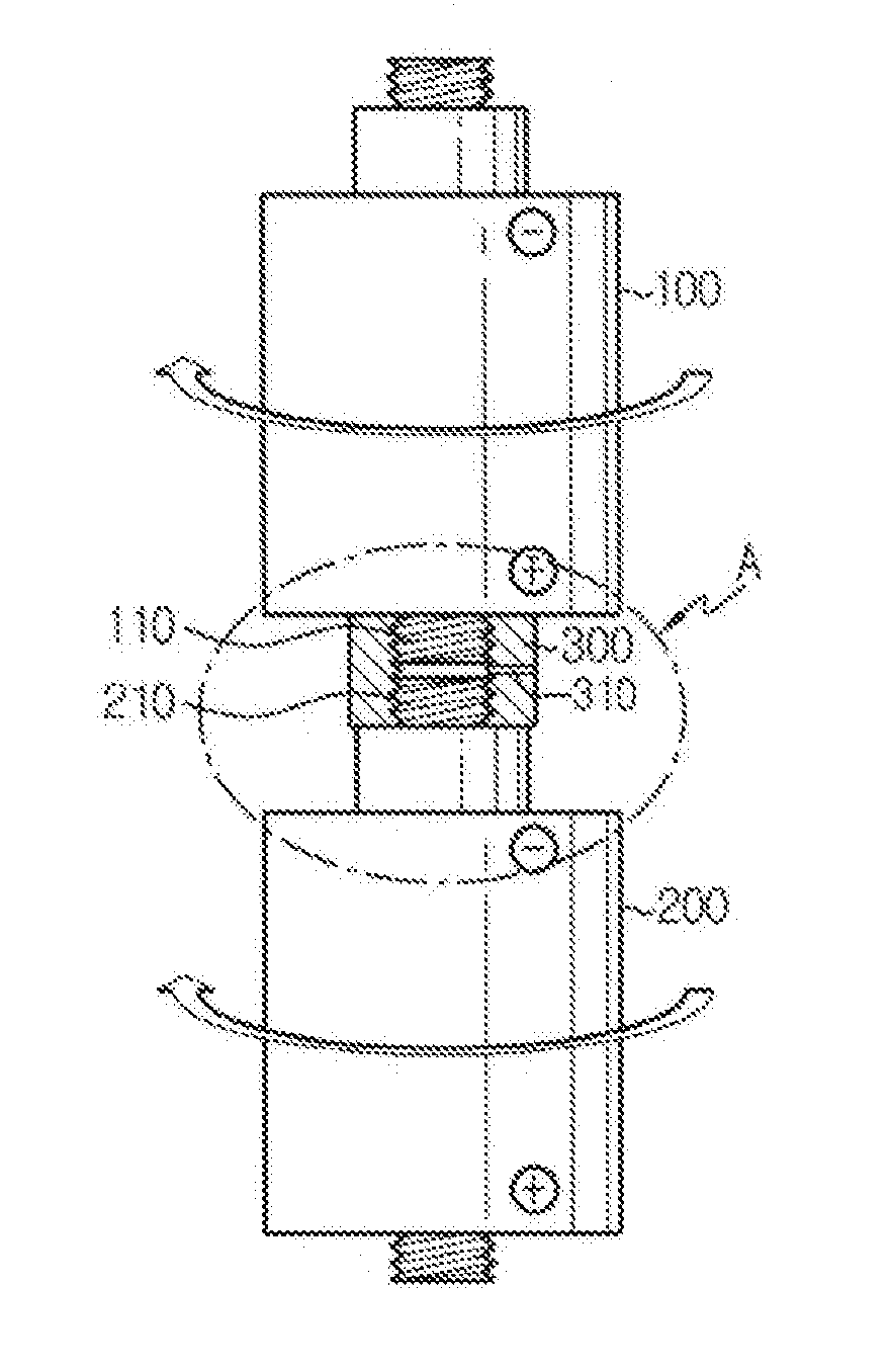
An ultra capacitor module includes a first ultra capacitor having a first polar terminal provided with a screw thread A formed on an outer peripheral surface, a second ultra capacitor having a second polar terminal provided with a screw thread A formed on an outer peripheral surface, and a connecting member having a screw hole B formed corresponding to the screw thread A on an inner peripheral surface through which the first polar terminal is inserted from one side and the second polar terminal is inserted from the other side to connect the first and second ultra capacitors in series and having a gas emission hole formed from a center to an outer surface.

Description

TECHNICAL FIELD[0001]The present disclosure relates to an ultra capacitor module, and more particularly, to an ultra capacitor module allowing easy connection between ultra capacitors and with an improved connecting structure of a balancing board.[0002]The present application claims priority to Korean Patent Application No. 10-2013-0093635 filed on Aug. 7, 2013 in the Republic of Korea, Korean Patent Application No. 10-2013-0100930 filed on Aug. 26, 2013 in the Republic of Korea, Korean Patent Application No. 10-2014-0101308 filed on Aug. 6, 2014 in the Republic of Korea, and Korean Patent Application No. 10-2014-0101312 filed on Aug. 6, 2014 in the Republic of Korea, the disclosures of which are incorporated herein by reference.BACKGROUND ART[0003]Generally, a battery and a capacitor are a typical device for storing electrical energy.[0004]An ultra capacitor, also known as a super capacitor, has intermediate characteristics between an electrolytic condenser and a secondary battery,...

Claims


Application Information

Patent Timeline
Patent Type & Authority Applications(United States)
IPC IPC(8): H01G11/78H01R12/62H05K1/18
CPCH01G11/78H05K2201/10015H01R12/62H05K1/181Y02E60/13H01G11/10H01G11/18H01G11/76H01G11/82H01G2/06
Inventor YOO, YONG-HYEONLEE, JUNG-GUL
Owner LS MATERIALS CO LTD
Why Eureka
Try Eureka