A high efficiency stacked solar cell

Inactive Publication Date: 2016-06-30
NEWSOUTH INNOVATIONS PTY LTD
View PDF14 Cites 31 Cited by
  • Summary
  • Abstract
  • Description
  • Claims
  • Application Information

AI Technical Summary

Benefits of technology

[0010]Embodiments of the present invention combine the advantages of silicon solar cells with those of a Perovskite ce

Problems solved by technology

However, single junction silicon based solar cells have a theoretical efficiency limit of 29% and record efficiencies of approximately 25% have been dem

Method used


Image

  • A high efficiency stacked solar cell
  • A high efficiency stacked solar cell
  • A high efficiency stacked solar cell

Examples


Embodiment Construction

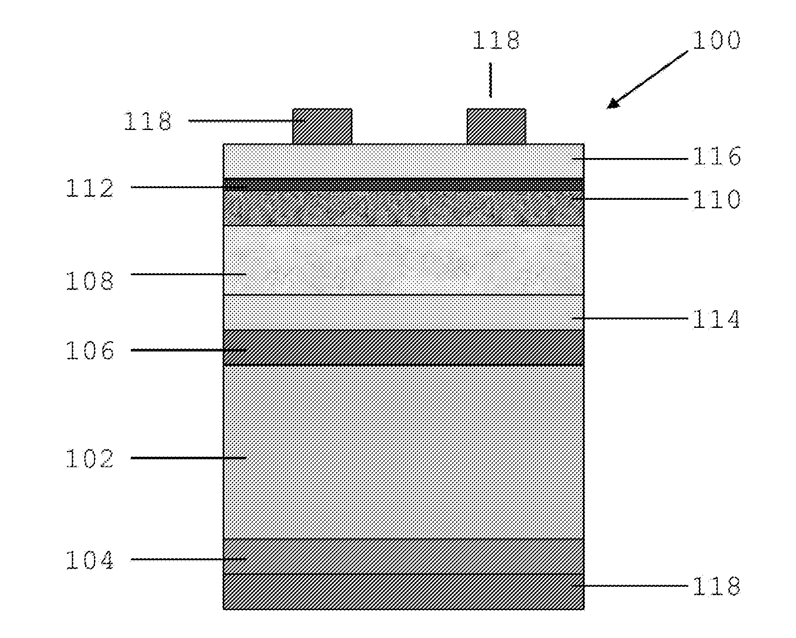
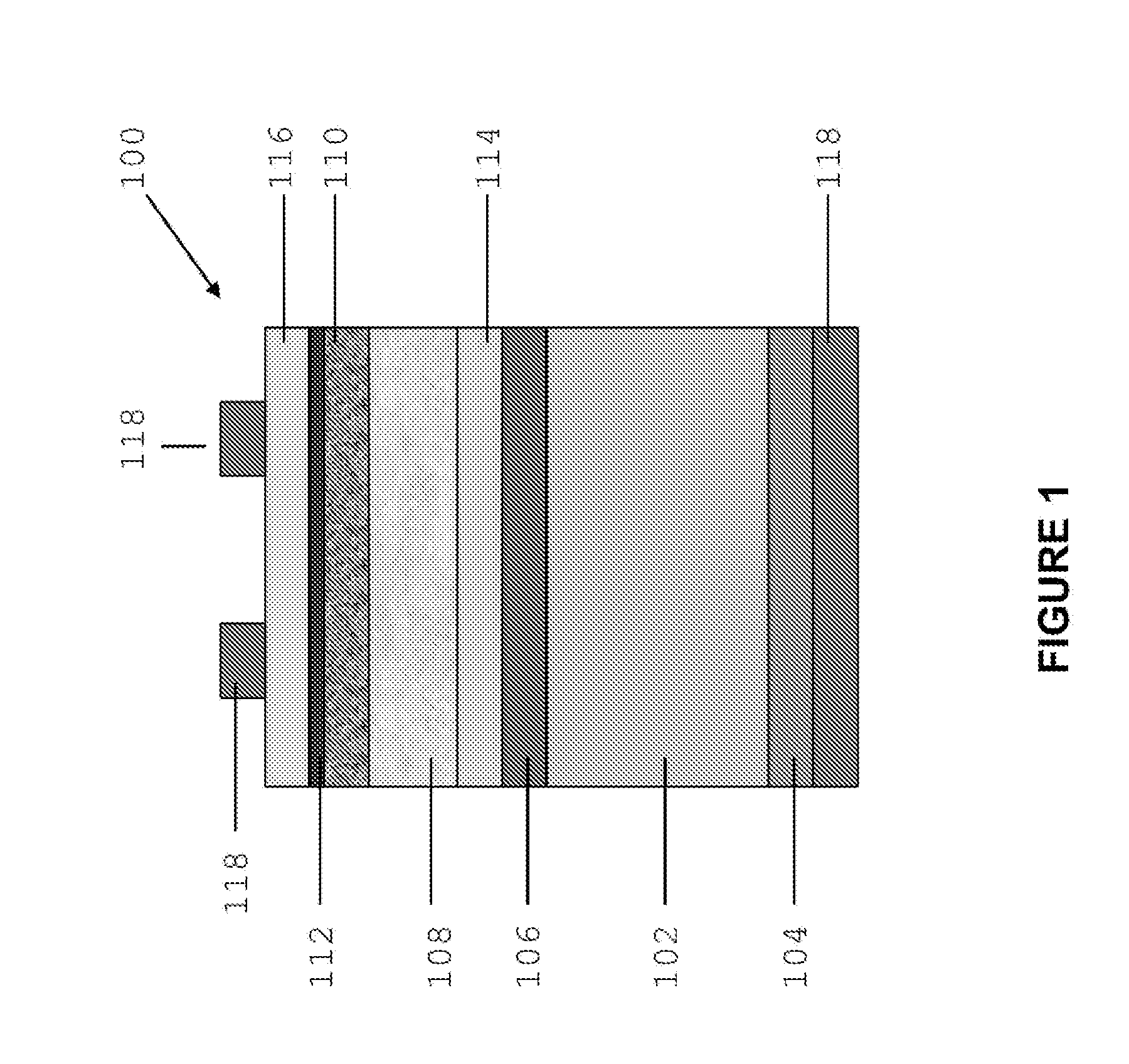
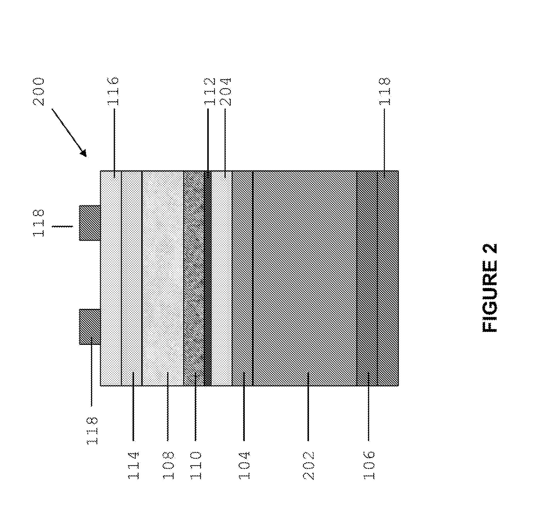
[0046]Embodiments of the present invention relate to high efficiency photovoltaic devices consisting of a series of solar cells stacked on top of each other. In particular, advantageous embodiments of the invention are related to a photovoltaic device consisting of a one of more thin films solar cells that include absorber materials with a Perovskite structure and are stacked on top of silicon single junction solar cell. In one embodiment, the device is configured as a tandem solar cell with a single homojunction silicon bottom cell and a thin film solid state Perovskite-based top cell. In these embodiments, the single homojunction cell comprises a silicon p-n junction which may be realised, for example, by diffusion of n-type dopants in a p-type silicon substrate or vice versa. Alternatively, the p-n junction may be realised using ion-implantation or epitaxy.

[0047]The single homojunction silicon bottom cell may be a single-crystalline cell realised on a crystalline silicon wafer. T...


PUM


Abstract

The present disclosure provides a photovoltaic device that has a photon receiving surface and a first single homojunction silicon solar cell. The first single homojunction silicon solar cell comprises two doped silicon portions with opposite polarities and has a first bandgap. The photovoltaic device further comprises a second solar cell structure that has an absorber material with a Perovskite structure and has a second bandgap that is larger than the first bandgap. The photovoltaic device is arranged such that each of the first and second solar cells absorb a portion of the photons that are received by the photon receiving surface.

Description

FIELD OF THE INVENTION[0001]The present invention generally relates to photovoltaic devices comprising multiple stacked solar cells.BACKGROUND OF THE INVENTION[0002]The cost of silicon solar cells has decreased dramatically in the past few years and it is to be expected that silicon technology will remain firmly entrenched over the coming decade as the dominant photovoltaic technology. Improvement of the conversion efficiency of such solar cells will continue to be a key factor. However, single junction silicon based solar cells have a theoretical efficiency limit of 29% and record efficiencies of approximately 25% have been demonstrated for laboratory-based solar cells.[0003]To further increase the efficiency of silicon based solar cells, the most promising approach is to stack cells of different materials on top of a silicon-based solar cell. By stacking a further solar cell on a silicon-based solar cell, the theoretically possible performance increases from 29% to 42.5%. By stack...

Claims


Application Information

Patent Timeline
IPC IPC(8): H01L31/0687H01L31/028H01L31/032H01L31/18
CPCH01L31/0687H01L31/1804H01L31/032H01L31/028H01L31/18Y02E10/549Y02E10/544Y02E10/547Y02P70/50H10K30/57H10K30/10H10K85/50
Inventor GREEN, MARTIN ANDREW
Owner NEWSOUTH INNOVATIONS PTY LTD
Why Eureka
Try Eureka