Device for in-vitro modelling in-vivo tissues of organs

a tissue and organ technology, applied in the field of organ tissue invitro modelling devices, can solve the problems of poor human response, ethically controversial and costly, and inability to efficiently and reproducibly predict the toxicity and efficiency of compounds in humans before launch of expensive clinical trials, and achieve the effects of simple, compact and efficient device implementation, and pressure in the valv

Active Publication Date: 2016-07-07
UNIVERSITY OF BERN
View PDF2 Cites 15 Cited by
  • Summary
  • Abstract
  • Description
  • Claims
  • Application Information

AI Technical Summary

Benefits of technology

[0024]Furthermore, providing the actuation chamber with one or more limitation cavities allows for limiting the deflection of the actuation membrane and, in correspondence therewith, also of the culturing membrane. This can make the operation and setup of the device comparably easy since the deflection can be limited independent from the type and material of the culturing membrane. In other words, the deflection of the actuation membrane, which can correspond to the desired deflection of the culturing membrane or in-vitro barrier, can be geometrically limited by the design of the limitation cavity. As a result the stretching level of the cells cultured on the culturing membrane can be kept constant regardless of the cell culture confluence on the culturing membrane, of the presence of an air-liquid or a liquid-liquid interface and to a certain extent to the mechanical properties of the culturing membrane. By restraining the deflection of the actuation membrane, the batch to batch variations of the culturing membrane material's visco-elastic properties and the variation of the actuation membrane geometry can be circumvented to a large extent. As a result a required actuation pressure does not mandatorily need to be accurately controlled which can provide for a calibration free actuation. Also, this set-up allows to indirectly creating small and accurate pressures that are required to stretch the cells cultured on the culturing membrane, by deflecting the, e.g., thicker actuation membrane with a higher pressure.
[0056]Preferably, the device comprises a control unit adapted to adjust and monitor operation properties of the device. Thereby, the control unit preferably is adapted to control a medium flow through the at least one culturing chamber. The control unit preferably is further adapted to control cell injection into the at least one culturing chamber, for instance by controlling the concentration of the cell loaded on the membrane or the density of the adherent or confluent cells cultured on the membrane. Also, the control unit preferably is adapted to control a pressure inside the at least one actuation chamber. The control unit can also control the pressure in the valve(s) that isolate the culturing chamber. Such a control unit allows for efficiently operating the device. It can be particularly implemented as or comprising a computer.

Problems solved by technology

One important issue that needs to be addressed is the lack of efficient and reproducible drug discovery models able to predict toxicity and efficiency of compounds in humans prior to launch expensive clinical trials.
The latter poorly predict the human response, are ethically controversial and costly.
However, the absence of efficient and reproducible in-vitro models able to predict the toxicity of chemical compounds in humans is one hurdle that needs to be tackled in toxicology testing.
This can importantly hamper the epithelial endothelial signalling.
However, the actuation principle shown in WO2010 / 009307 A2 suffers important limitations.
At least these factors do not allow the precise control of the stretching level of the thin membrane and ultimately of the cells that are cultured on this membrane.
Therefore, the fabrication processes of the device must be extremely accurate which increases the production costs and / or may require a costly calibration of the stress in the membrane in function of the applied pressure for each device.
Furthermore, several aspects of this device only approximately reproduce the basement membrane of the lung alveoli and its deformation.
Indeed, the unidirectional stretching generated by the adjacent channels of this device does not correspond to the three-directional stretching that takes place in the human lung.
The shown device is not equipped with a porous membrane and thus is not allowing to mimic the complexity of the alveolar membrane by reproducing the air-blood barrier.
Further, it does not allow for the culture of cells at the side of the membrane where the pin pushes to deform it since the direct contact of the pin with the membrane would squeeze the cells and damage them.
This means that this system does not allow mimicking the co-culture system typical to in-vitro barriers even if one would integrate a porous membrane.
An additional limitation of the system described in US 2010 / 0233799 A1, also due to the direct contact of the pin against the membrane, is the obvious absence of space between the pin and the membrane.
This prevents from providing sufficient space for physiological medium and as a consequence cells could not be perfused.
Since no physiological solution can be provided to the cells from the bottom of the membrane, the physiological medium needs to be provided from the top of the membrane where the cells are cultured, meaning that no air-liquid interface (ALI) condition can be set up in this system.
Another downside of the system of US 2010 / 0233799 A1 is that the observation of the cells from the bottom of the chip is not possible with a non-transparent pin.

Method used


Image

  • Device for in-vitro modelling in-vivo tissues of organs
  • Device for in-vitro modelling in-vivo tissues of organs
  • Device for in-vitro modelling in-vivo tissues of organs

Examples


first embodiment

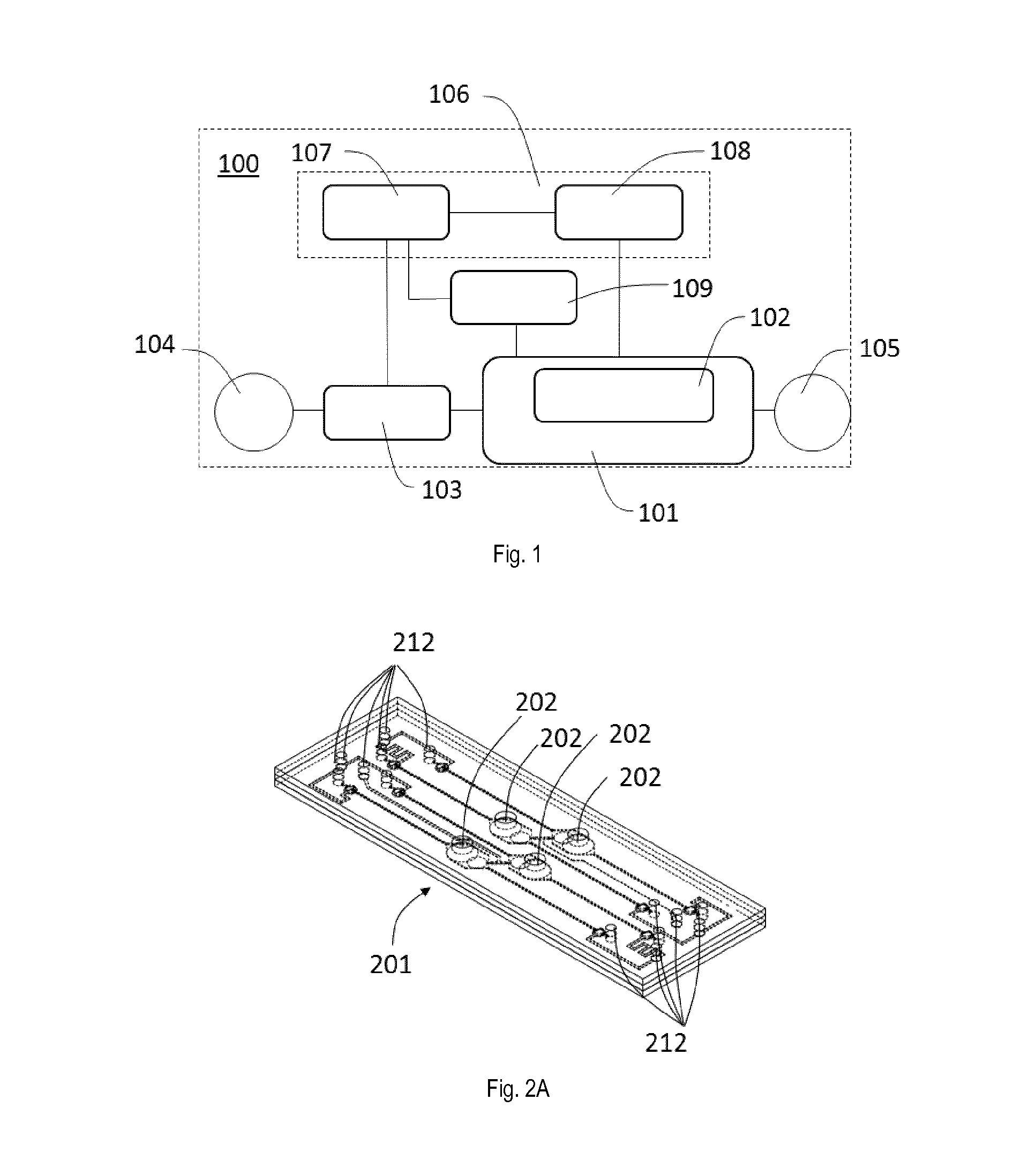
[0101]FIG. 1 shows a system 100 for in-vitro modelling in-vivo tissues of organs as a device according to the invention. The system 100 has a bioartificial organ device 101 with a culturing membrane as an in-vitro-barrier 102. It further comprises a setup 106 having one or more CPUs 107 of a control unit connected to one or more pressure sources 108, a cell injector 109 and one or more pumps 103. The one or more pressure sources 108 and the cell injector 109 are controlled by the one or more CPUs 107 and are connected to the bioartificial organ device 101. The one or more pumps 103 are arranged in between a source reservoir 104 as medium source and the bioartificial organ device 101 which is also connected to a collecting reservoir 105 as medium sink. By means of the one or more pumps 103 and the one or more CPUs 107 a fluid flow from the source reservoir 104 to the collecting reservoir 105 via the bioartificial organ device 101 can be controlled. Although only one bioartificial org...

second embodiment

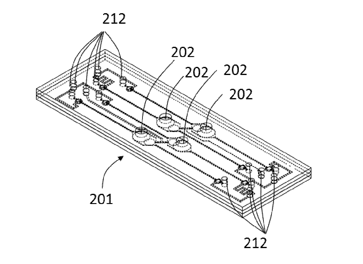
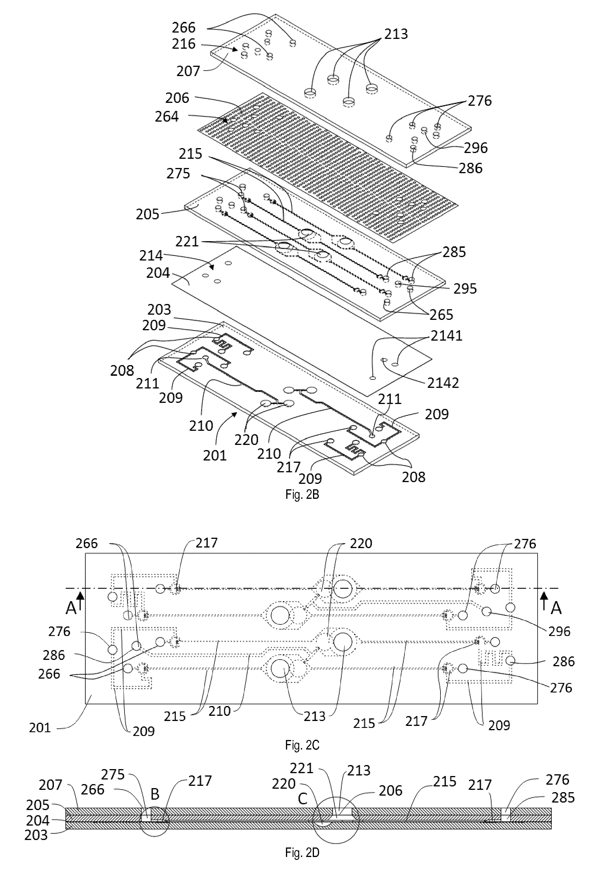
[0110]FIGS. 2A and 2B illustrate a perspective view of a bioartificial organ device 201 of a device according to the invention in an assembled view and in an exploded view. The bioartificial organ device 201 is equipped with four in-vitro barriers 202 and includes a plurality of ports 212 that will be described in more detail below. The bioartificial organ device 201 is composed by different body portions, including a bottom body 203 as third body portion, an actuation membrane 204, an intermediate body 205 as second body portion, a thin porous culturing membrane 206 and a top body 207 as first body portion. Each of the bottom body 203, intermediate body 205 and top body 207 has an essentially rectangular plate-like shape. Each of the actuation membrane 204 and the culturing membrane 206 has an essentially rectangular shape.

[0111]The bottom body 203 includes two deflection actuation channels 210 and four valve actuation channels 209 in which a fluid, preferably air, is arranged to c...

third embodiment

[0136]FIGS. 3A and 3B show views of a bioartificial organ device 2010 of a device according to the invention. In general, the bioartificial organ device 2010 is essentially identically embodied as the bioartificial organ device 201 described above. The bioartificial organ device 2010 comprises a bottom body 2030 as a third body portion with deflection actuation channels 2100, valve actuation channels, microvalve chambers 2170 and actuation chambers 2200 having limitation cavities. On top of the bottom body 2030 an intermediate body 2050 with perfusion channels 2150 and culturing chambers 2210 is arranged as second body portion wherein between the bottom body 2030 and the intermediate body 2050 an actuation membrane 2040 is sandwiched. On top of the intermediate body 2050 a top body 2070 with access chambers 2130 is arranged as first body portion, wherein between the intermediate body 2050 and the top body 2070 a thin porous culturing membrane 2060 is sandwiched. Sections of the cult...


PUM

PropertyMeasurementUnit
thicknessesaaaaaaaaaa
thicknessaaaaaaaaaa
thicknessaaaaaaaaaa

Abstract

A device (201) for in-vitro modelling in-vivo tissues of organs, comprises: a first body portion (207) with at least one access chamber (213), a second body portion (205) with at least one culturing chamber (221), and a culturing membrane (206) dividing the at least one access chamber (213) from the culturing chamber (221). The device further comprises a third body portion (203) with at least one actuation chamber (220) having at least one limitation cavity, and an actuation membrane (204) dividing the at least one culturing chamber (221) from the at least one actuation chamber (220). With the device according to the invention a robust actuation system can be provided that does not depend on the mechanical properties of the actuation membrane material, nor on the pressure, and that allows to mimic three-dimensional deformations of the tissue, in particular of lung alveoli.

Description

TECHNICAL FIELD[0001]The present invention relates to a device according to the preamble of independent claim 1. Such a device comprising a first body portion with at least one access chamber, a second body portion with at least one culturing chamber, and a culturing membrane dividing the at least one access chamber from the culturing chamber can be used for in-vitro modelling in-vivo tissues of organs.BACKGROUND ART[0002]The pharmaceutical sector is currently experiencing efforts in rethinking the way research and development can be performed more efficiently. One important issue that needs to be addressed is the lack of efficient and reproducible drug discovery models able to predict toxicity and efficiency of compounds in humans prior to launch expensive clinical trials.[0003]Similarly, chemical companies as well as public and regulation authorities are looking for alternative in-vitro methods to animal testing. The latter poorly predict the human response, are ethically controve...

Claims


Application Information

Patent Timeline
Patent Type & Authority Applications(United States)
IPC IPC(8): C12M3/00C12M1/12C12M1/34C12M1/00
CPCC12M21/08C12M41/40C12M25/02C12M29/10C12M25/04C12M35/04C12M35/08
Inventor GUENAT, OLIVIER THIERRYFELDER, MARCELSTUCKI, ANDREASSTUCKI, JANICK DANIELGEISER, THOMAS
Owner UNIVERSITY OF BERN
Why Eureka
Try Eureka