X-ray imaging device

a technology of x-ray imaging and length information, which is applied in the field of x-ray imaging devices, can solve the problems of low accuracy level of length information of general panorama images, general three-dimensional x-ray imaging devices, projection images, etc., and achieves short imaging time, small area, and high level accuracy.

Active Publication Date: 2016-07-14
VA TECHNOLOGIE +1
View PDF4 Cites 11 Cited by
  • Summary
  • Abstract
  • Description
  • Claims
  • Application Information

AI Technical Summary

Benefits of technology

[0010]The present invention is intended to provide an X-ray imaging device, the device receiving multidirectional X-rays that have passed an object to be imaged by using a detector having a small width, and the device obtaining projection data for producing a three-dimensional image of the object. Accordingly, the device can display a tomogram and a three-dimensional image that have high level accuracy for a desired area by using a detector having a small area, using low dose of irradiated X-rays, and having short imaging time, compared to existing X-ray Computerized Tomography (CT) imaging.
[0011]Furthermore, the present invention can provide an accurate and intuitive image for a position and a direction desired by a user, such as a panorama image, by using a tomogram and a three-dimensional image for a part desired to be analyzed by a user. Further, since problems of a projection image, such as overlapping teeth and blurring by the cervical spine, do not exist in the image according to the present invention, it is advantageous in that the device can be widely used.
[0012]Furthermore, a digital X-ray panorama detector according to the related art is configured such that an X-ray film thereof is replaced only. However, in the present invention, a three-dimensional panorama digital image can be provided.

Problems solved by technology

However, an accuracy level of length information of a general panorama image is low, and there is a limitation of a projection image, such as an overlap of teeth and blurring by the cervical spine. FIG. 2 is a view illustrating an example, commonly used in the dental field, of an X-ray computerized tomography (CT) image for a head.
However, a general three-dimensional X-ray image device is problematic in that the amount of radiation exposed to a patient is relatively high and an expensive large area detector is required.
Generally, since a price of a detector is considerably increased depending on an area thereof, it is not possible for an X-ray device for producing a three-dimensional image to avoid cost increase caused by a large area detector, thereby increasing in equipment cost.
Further, when an area of a sensor is increased, the weight of equipment is increased.
Thus, it is problematic in that a size of equipment should be larger because a focal spot to detector distance (FDD) is increased as well so that the FOV can be ensured.

Method used


Image

  • X-ray imaging device
  • X-ray imaging device
  • X-ray imaging device

Examples


Embodiment Construction

[0030]Hereinafter, embodiments of the present invention are described in detail with reference to the accompanying drawings.

[0031]Although embodiments of an X-ray imaging device for dental use according to the present invention are disclosed below for illustrative purposes, the scope of the present invention is not limited thereto. Further, those skilled in the art will easily appreciate that the scope of the present invention are applicable to all the related X-ray imaging devices with reference to descriptions below. Further, the accompanying drawings are illustrated for reference to understand the scope of the present invention, and sizes of respective components and mutual sizes between components shown in the accompanying drawings may be different from the actual sizes.

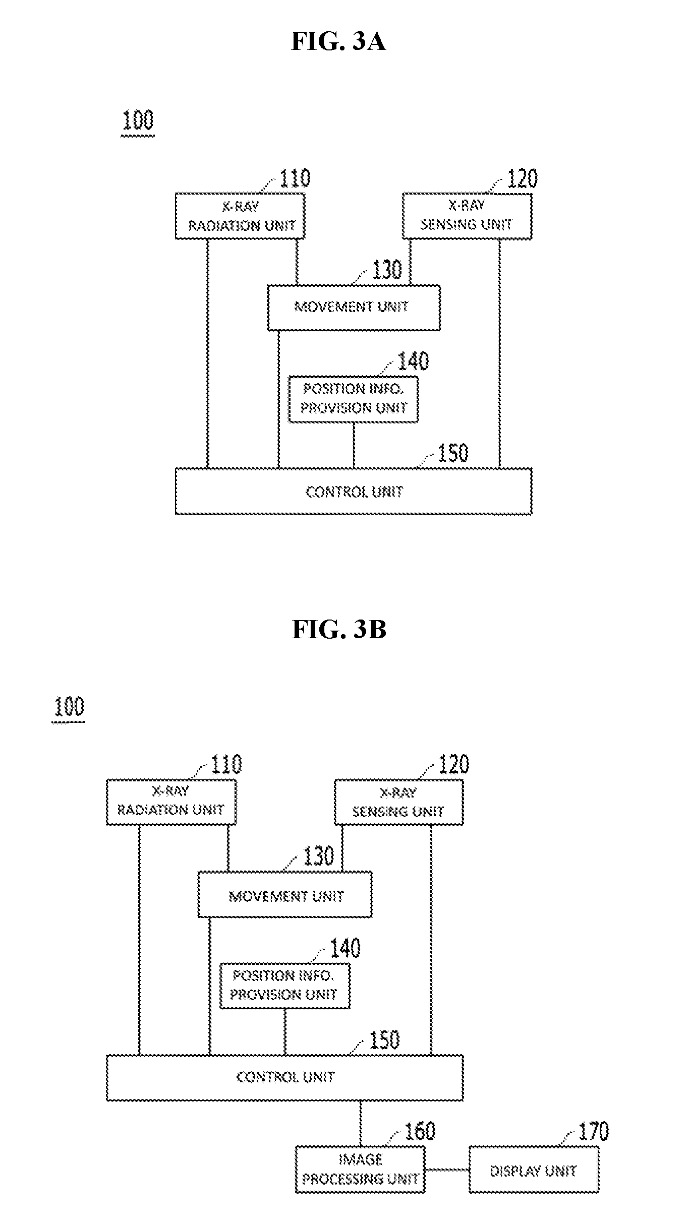
[0032]FIG. 3a is a schematic view illustrating a configuration of an X-ray imaging device 100 according to an embodiment of the present invention. The X-ray imaging device 100 includes an X-ray radiation unit 110...


PUM


Abstract

Disclosed is an X-ray imaging device, the device including: an X-ray radiation unit for radiating X-rays to the predetermined target areas of an object to be imaged in respective imaging positions; an X-ray sensing unit for receiving the X-rays; a movement unit for arranging the X-ray radiation unit and the X-ray sensing unit to allow the X-ray radiation unit and the X-ray sensing unit to face each other in the respective imaging positions, with the object located therebetween; a position information provision unit for providing position information of the X-ray radiation unit and the X-ray sensing unit, position information of the variable rotary shaft, and position information of the target areas; a control unit for controlling the X-ray radiation unit, the X-ray sensing unit, and the movement unit; and an image processing unit for producing three-dimensional images of the object from the projection data.

Description

TECHNICAL FIELD[0001]The present invention generally relates to an X-ray imaging device. More particularly, the present invention relates to an X-ray imaging device in which a three-dimensional image can be produced by using a detector having a small width.BACKGROUND ART[0002]In general, X-rays radiated to an object to be imaged are attenuated depending on an X-ray attenuation coefficient of a substance located on a radiating path by photoelectric effect or Compton scattering. X-ray imaging is a radiation photographing method using a penetration characteristic of X-rays, and image information of an internal structure of the object is provided based on the amount of accumulated attenuation in a process of penetrating through the object. Generally, an X-ray imaging device includes an X-ray source radiating the X-rays, an X-ray detector detecting the X-rays penetrating through the object while allowing the X-ray detector and the X-ray source to face each other with the object located t...

Claims


Application Information

Patent Timeline
Patent Type & Authority Applications(United States)
IPC IPC(8): A61B6/14G06T15/00G06T15/08A61B6/00G06T7/00
CPCA61B6/14A61B6/466G06T7/0012G06T2200/04G06T15/005G06T2207/30036G06T2207/10116G06T15/08A61B6/032A61B6/035A61B6/4441A61B6/463A61B6/5223A61B6/4452A61B6/5205
Inventor CHOI, SUNG ILKIM, TAE WOOHONG, TAE KI
Owner VA TECHNOLOGIE
Why Eureka
Try Eureka