Energy generation from waste heat using the carbon carrier thermodynamic cycle

a technology of thermodynamic cycle and waste heat, applied in the direction of heating fuel, energy-efficient heating/cooling, other heat production devices, etc., can solve the problem of high cost of used h

Inactive Publication Date: 2016-07-14
CLIMEON AB
View PDF6 Cites 22 Cited by
  • Summary
  • Abstract
  • Description
  • Claims
  • Application Information

AI Technical Summary

Problems solved by technology

The improvement needs for heat pumps are evident from the following: a) Lower paraffins as working fluids are flammable and pose therefore risks. b) The often used HFC are expensive, and whilst they are not dangerous for the earth's ozone layer, they contribute to the greenhouse effect.

Method used


Image

  • Energy generation from waste heat using the carbon carrier thermodynamic cycle
  • Energy generation from waste heat using the carbon carrier thermodynamic cycle
  • Energy generation from waste heat using the carbon carrier thermodynamic cycle

Examples


Embodiment Construction

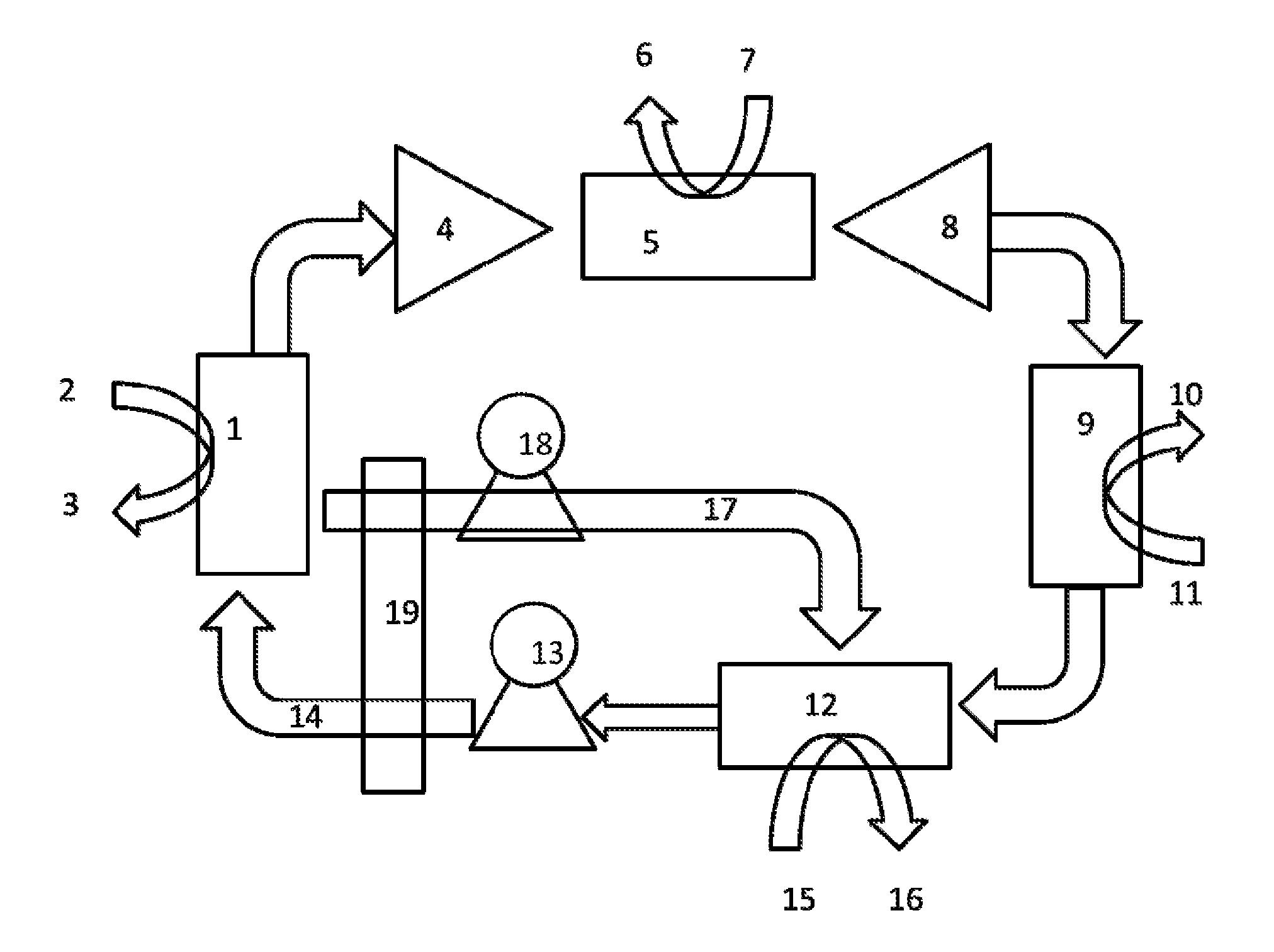
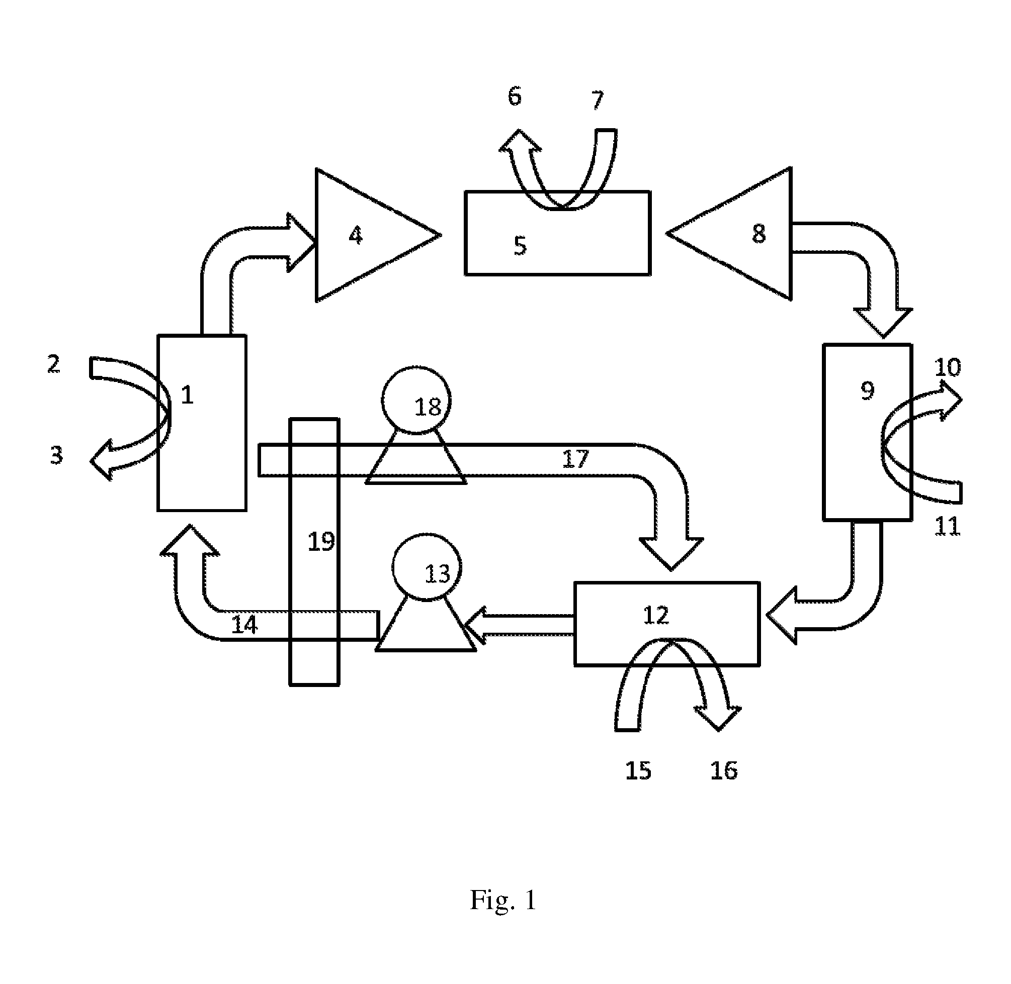
[0026]The heat pump is shown in one embodiment in FIG. 1.

[0027]The heat pump according to the invention operates as follows: heat, e.g. geothermal or waste heat of e.g. 40-70° C., is supplied via heat exchanger (1) (flow in at (2), flow out at (3) to a mixture of CO2 and absorbent (CO2-rich absorbent mix). This mixture, as described in the a.m. disclosures and essentially comprising amines (including ammonia, NH3) and CO2, e.g. in the form of carbonates or carbamates, is pumped using pump (13) into the heat exchanger through pipe (14). In the desorber (1), CO2 gas is desorbed at a pressure dependent on the nature of the absorbent, but typically being 0.3 to 2 bar. CO2 gas is compressed in compressor (4) to a higher pressure, e.g. 5-20 bar, and the CO2 is heated by compression. This heat is extracted in heat exchanger (5), and the heat is transferred to a medium through pipes (6) and (7). The colder gas is expanded through an expansion machine (8) which preferably is mechanically cou...


PUM


Abstract

The invention relates to a method is provided which allows the generation of high temperatures, e.g. above 120° C. and maximum 200° C. and low temperatures, e.g. below minimum minus 20° C., from waste heat or geothermal heat or similar heat sources having a temperature of between 20 and 70° C. The method may use essentially pure carbon dioxide as primary working fluid in an essentially closed loop as described in previous disclosures, alternatively low boiling solvents are employed. The common feature of different embodiments is that the system operates at least partly, specifically in the absorber or cold side of the process, below atmospheric pressure (1 bar). In the method a heat pump or heat transformer is realized within the technical boundaries mentioned above. The invention also relates to the use of the method in combination with a district heating system for elevating the temperature of the district heating medium or for electricity production on demand.

Description

FIELD OF THE INVENTION[0001]The present invention relates to a method for generation of energy where a heat source supplies thermal energy in the range 30-80° C. to a Rankine cycle including a desorber on the hot side, an absorber or liquefier on the cold side, heat exchangers and at least one compressor and at least one pump for working fluid, and at least one of the following product streams is obtained:[0002]thermal energy in the range +90, +100, +120 and maximum +200° C.,[0003]thermal energy in the range +15, +10, +5, 0, −5 and minimum −20° C.,[0004]electricity from the decompression of CO2 or a working fluid following the extraction of heat.BACKGROUND OF THE INVENTION[0005]Reference is made to PCT / SE / 2012 / 050319 or WO 2012 / 128715 with priority from SE 1100208-6 (filed Mar. 22, 2011), U.S. application 61 / 468 474 (filed Mar. 28, 2011) and SE 1100596-4 (filed 16.08.2011), these documents are included by way of reference. These documents describe a novel thermodynamic cycle for ene...

Claims


Application Information

Patent Timeline
Patent Type & Authority Applications(United States)
IPC IPC(8): F01K25/08F24J3/08
CPCF24J3/08F01K25/08F01K25/065F25B11/02F25B15/02F25B25/02F25B27/02F25B30/04F24T10/00Y02B30/62Y02E10/10Y02A30/27Y02A30/274
Inventor KARTHAUSER, JOACHIM
Owner CLIMEON AB
Why Eureka
Try Eureka