System and method for linear non-reciprocal communication and isolation

Inactive Publication Date: 2016-07-21
THE BOARD OF TRUSTEES OF THE UNIV OF ILLINOIS
View PDF0 Cites 10 Cited by
  • Summary
  • Abstract
  • Description
  • Claims
  • Application Information

AI Technical Summary

Problems solved by technology

Dynamic optical non-reciprocity has also been achieved through optically-pumped Brillouin scattering and through electrically-driven interband transitions, but these are nonlinear effects requiring subsequent optical filtering.

Method used


Image

  • System and method for linear non-reciprocal communication and isolation
  • System and method for linear non-reciprocal communication and isolation
  • System and method for linear non-reciprocal communication and isolation

Examples


Embodiment Construction

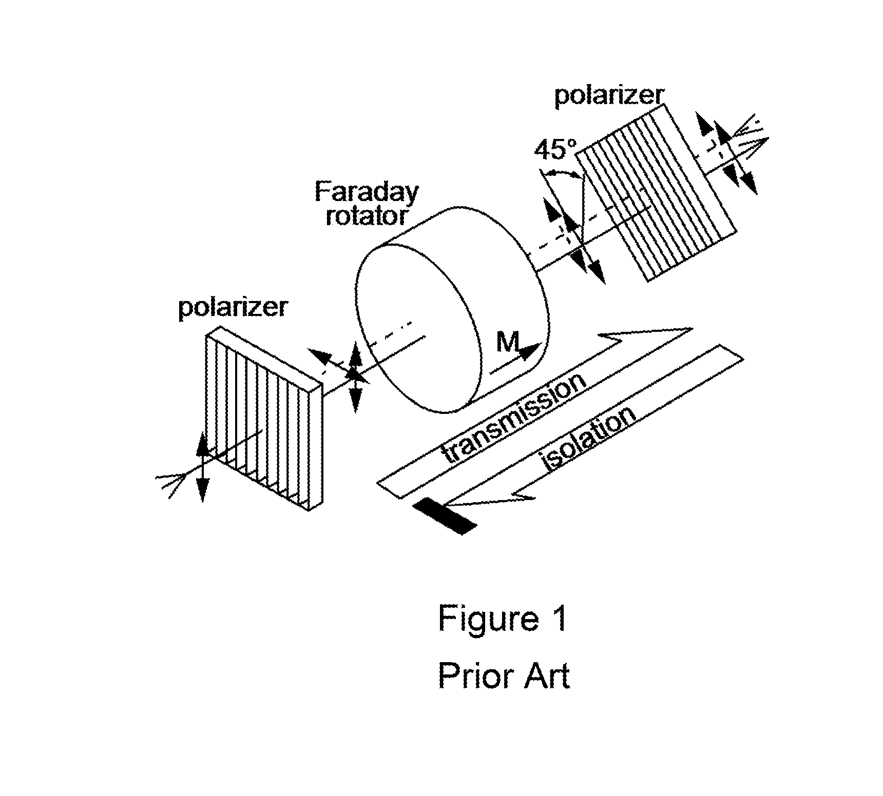
[0015]Reciprocity, or time-reversal symmetry, is an inescapable property in electromagnetic, acoustic, and thermodynamic systems. In the optical context, non-reciprocal behavior can be obtained using magneto-optical effects. An example of non-reciprocal behavior is to allow light to travel forwards but not backwards in a waveguide—such a device is called an “isolator”. Until now, however, this requires the use of specialized magneto-optic materials that are challenging to implement at the chip-scale, and biasing magnetic fields that are not suitable for many applications. Previously studied magnet-free alternatives for non-reciprocity are either intrinsically not linear or are experimentally unproven. It is desirable to achieve magnet-free nonreciprocity with optical or acoustic or electronic control.

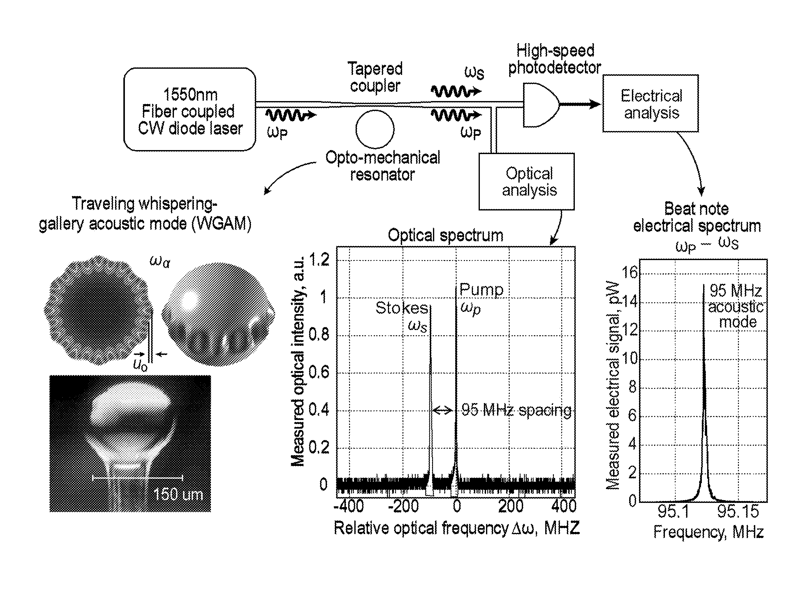
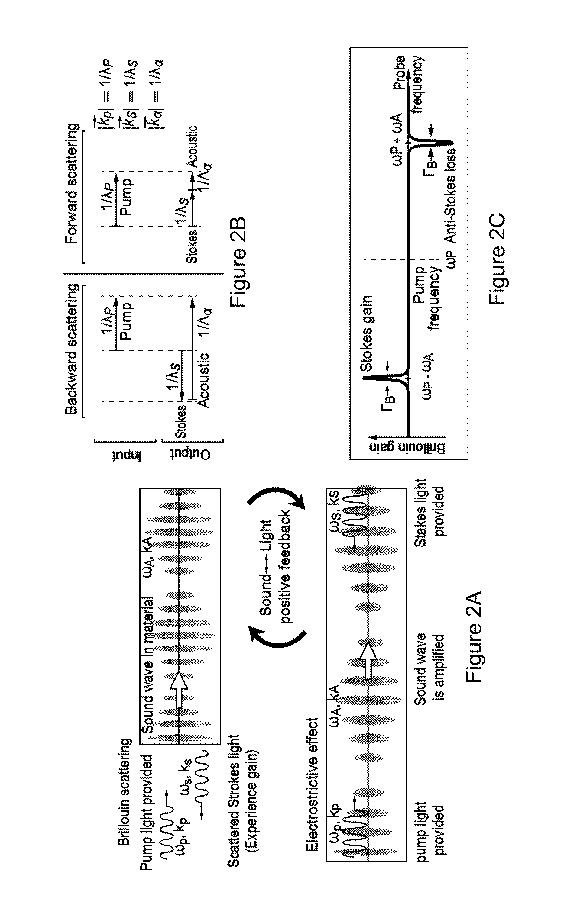
[0016]The systems and methods relate to traveling-wave Brillouin scattering induced optical interference mechanism that can be used to achieve linear non-reciprocal behavior. Isolators ...


PUM


Abstract

A system and method includes a waveguide for guiding an energy received from a laser. A resonator couples with the waveguide. A signal generator (pump) generates a spatiotemporal pattern wave in the resonator. The spatiotemporal pattern wave produces a wave interaction. Where an interaction between the signal, the spatiotemporal pattern wave and the wave interaction produce linear non-reciprocal behavior in the signal wave.

Description

CROSS-REFERENCE TO RELATED APPLICATION[0001]This application claims the benefit of U.S. Provisional Application Ser. No. 62 / 104,391, filed Jan. 16, 2015, which is incorporated in its entirety herein.GOVERNMENT LICENSE RIGHTS[0002]This invention was made with government support under grant number ECCS-1408539 awarded by the US National Science Foundation (NSF), and grant number FA9550-14-1-0217 awarded by the US Air Force Office for Scientific Research (AFOSR). The government has certain rights in the invention.BACKGROUND[0003]Breaking time reversal symmetry, e.g., non-reciprocity, is necessary for optical isolators and circulators, e.g., in the context of chip-scale optical communications, amplifiers, and sensors. Presently, non-reciprocal optical devices, such as isolators and circulators, are almost exclusively built using the Faraday polarization rotation effect. The Faraday effect is a magneto-optical phenomenon through which direction-asymmetric polarization rotation can be ach...

Claims


Application Information

Patent Timeline
Patent Type & Authority Applications(United States)
IPC IPC(8): G02B6/293G10K11/18H01P1/219
CPCG02B6/29341G10K11/18H01P1/219G02B6/2746H01S3/083H01S3/30G10K15/046G02F1/365G02F2203/15
Inventor BAHL, GAURAV
Owner THE BOARD OF TRUSTEES OF THE UNIV OF ILLINOIS
Why Eureka
Try Eureka