LED tube lamp

Active Publication Date: 2016-07-28
JIAXING SUPER LIGHTING ELECTRIC APPLIANCE
View PDF8 Cites 40 Cited by
  • Summary
  • Abstract
  • Description
  • Claims
  • Application Information

AI Technical Summary

Benefits of technology

[0024]In the above-mentioned embodiments, the glass lamp tube includes the main body region, the rear end region, and the two-arc-shaped transition region connecting the main body region and the rear end region. Therefore, a height difference between the rear end region and the main body region is formed to avoid adhesives applied on the rear end region being overflowed onto the main body region, and thereby saves manpower for removing the overflowed adhesive and increases productivity. Since the glass lamp tube includes the two-arc-shaped transition region, the bendable circuit sheet is necessary such that it can be mounted on the inner surface of the glass lamp tube as well as extending into the end cap to be connected to the power supply.
[0025]By applying electromagnetic field to the magnetic metal member, an electrical current will be induced in the magnetic met

Problems solved by technology

However, existing LED tube lamps have certain drawbacks.
First, the typical circuit board is rigid and allows the entire lamp tube to maintain a line tube configuration when the lamp tube is partially ruptured or broken, and this gives the user a false impression that the LED tube lamp remains usable and is likely to cause the user to be electrically shocked upon handling or installation of the LED tube lamp.
Second, the rigid circuit board is typically electrically connected with the end caps by way of wire bonding, in which the wires may be easily damaged and even broken due to any move during manufacturing, transportation, and usage of the LED tube lamp and therefore may disable the LED tube lamp.
Third, the lamp tube and the end caps are often secured together by using adhesive, and it is hard to prevent the buildup of excess (overflown) adhesive residues.
This may cause light blockage as well as an unpleasant aesthetic appearanc

Method used


Image

  • LED tube lamp
  • LED tube lamp
  • LED tube lamp

Examples


Example

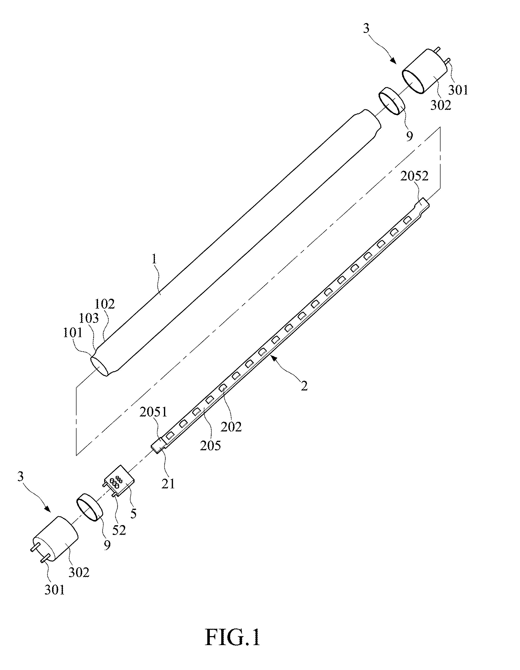
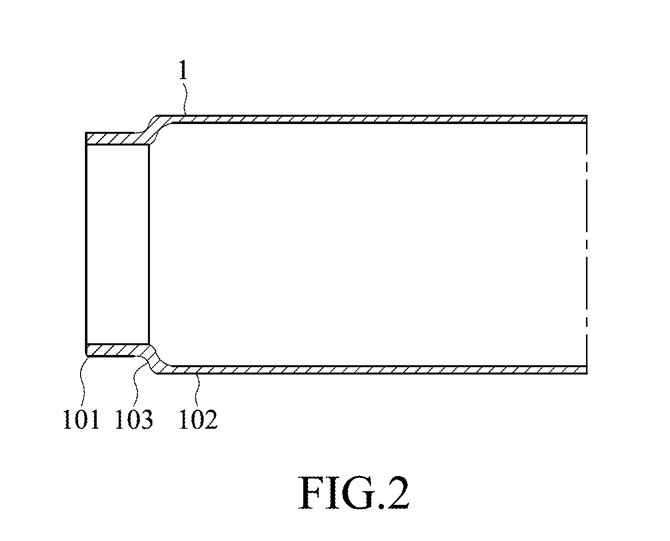
[0058]Referring to FIG. 1 and FIG. 2, an LED tube lamp in accordance with a first embodiment of the present invention includes a glass lamp tube 1, two end caps 3 respectively disposed at two ends of the glass lamp tube 1, a power supply 5, and an LED light strip 2 disposed inside the glass lamp tube 1. The glass lamp tube 1 extending in a first direction along a length of the glass lamp tube 1 includes a main body region 102, a rear end region 101, and a two-arc-shaped transition region 103 connecting the main body region and the rear end region 101, the main body region 102 and the rear end region 101 are substantially parallel. The outer diameter of the rear end region 101 is smaller than that of the main body region 102, therefore, a height difference between the rear end region 101 and the main body region 102 is formed to avoid adhesives applied on the rear end region 101 being overflowed onto the main body region 102, and thereby saves manpower for removing the overflowed adh...

Example

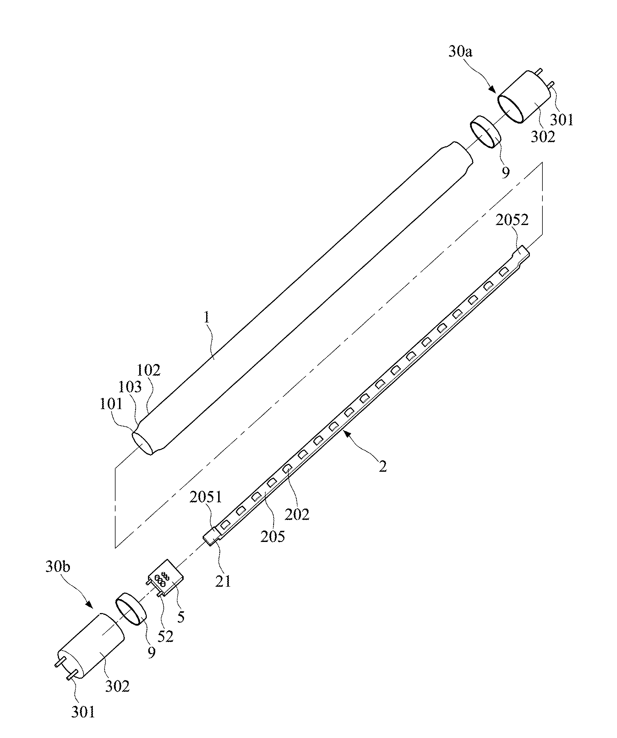
[0064]Referring to FIG. 2 and FIG. 14, an LED tube lamp in accordance with a second embodiment of the present invention includes a glass lamp tube 1, end cap 30a and end cap 30b, a power supply 5, and an LED light strip 2 disposed inside the glass lamp tube 1. The glass lamp tube 1 extending in a first direction along a length of the glass lamp tube 1 includes a main body region 102, a rear end region 101, and a two-arc-shaped transition region 103 connecting the main body region 102 and the rear end region 101, the main body region 102 and the rear end region 101 are substantially parallel. The outer diameter of the rear end region 101 is smaller than that of the main body region 102, therefore, a height difference between the rear end region 101 and the main body region 102 is formed to avoid adhesives applied on the rear end region 101 being overflowed onto the main body region 102, and thereby saves manpower for removing the overflowed adhesive and increases productivity.

[0065]R...

Example

[0072]Referring to FIG. 22 to FIG. 24, the end cap 3 in the third embodiment includes a socket 305 for connection with a power supply 5. The glass lamp tube 1 and the end caps 3 are secured by a hot melt adhesive. The power supply 5 is provided inside the end cap 3 and has a metal pin 52 at one end, while the end cap 3 has a hollow conductive pin 301 to accommodate the metal pin 52 of the power supply 5. Referring to FIG. 6 and FIG. 22, the LED light strip 2 is disposed inside the glass lamp tube 1 with a plurality of LED light sources 202 mounted on the LED light strip 2. The LED light strip 2 has a bendable circuit sheet 205 electrically connecting the LED light sources 202 and the power supply 5. The length of the bendable circuit sheet 205 is larger than the length of the glass lamp tube 1, and the bendable circuit sheet 205 has a first end 2051 and a second end 2052 opposite to each other along the first direction, and at least the first end 2051 of the bendable circuit sheet 2...


PUM


Abstract

An LED tube lamp including a glass lamp tube, an LED light strip disposed inside the glass lamp tube, and an end cap attached over an end of glass lamp tube is disclosed. The glass lamp tube includes a main body region, a rear end region, and a two-arc-shaped transition region connecting the main body region and the rear end region. The LED light strip includes a bendable circuit sheet being longer than the glass lamp tube to form a freely extending end portion. In addition, the end cap has at least one opening on surface to dissipating heat resulting from power supply and/or the process of heating of a hot melt adhesive.

Description

CROSS-REFERENCE TO RELATED APPLICATIONS[0001]This application is a continuation-in-part (CIP) of U.S. patent application Ser. No. 14 / 865,387, filed on Sep. 25, 2015, which claims priority to Chinese Patent Applications No. CN 201410507660.9 filed on Sep. 28, 2014; CN 201410508899.8 filed on Sep. 28, 2014; CN 201410623355.6 filed on Nov. 6, 2014; CN 201410734425.5 filed on Dec. 5, 2014; CN 201510075925.7 filed on Feb. 23, 2015; CN201510104823.3 filed on Mar. 11, 2015; CN 201510134586.5 filed on 2015 / 3 / 26; CN201510133689.x filed on Mar. 25, 2015; CN 201510136796.8 filed on Mar. 27, 2015;CN201510173861.4 filed on Apr. 15, 2015;CN201510155807.7 filed on Apr. 3, 2015; CN201510193980.6 filed on Apr. 22, 2015; CN 201510372375.5 filed on Jun. 26, 2015; CN 201510259151.3 filed on May 19, 2015; CN201510268927.8 filed on May 22, 2015; CN201510284720.x filed on May 29, 2015; CN 201510338027.6 filed on Jun. 17, 2015; CN 201510315636.x filed on Jun. 10, 2015; CN 201510373492.3 filed on Jun. 26, 2...

Claims


Application Information

Patent Timeline
IPC IPC(8): F21K99/00F21V15/015F21V23/02F21V19/00F21V29/83F21V17/10H05B44/00
CPCF21K9/175F21V29/83F21V17/101F21Y2103/003F21V19/009F21V15/015F21V23/023F21V3/02F21V23/02F21V29/508F21Y2103/10F21Y2115/10F21K9/272F21K9/66H05K1/118H05K1/189H05K2201/10106H05B45/00H05B45/56
Inventor JIANG, TAO
Owner JIAXING SUPER LIGHTING ELECTRIC APPLIANCE
Why Eureka
Try Eureka