Fbg sensor for measuring maximum strain, manufacturing method and using method

a manufacturing method and sensor technology, applied in the field of fbg sensors, can solve the problems of inability to detect the maximum strain of the object to be measured using the residual strain of the coated material, the likelihood of breaking of the coatingless optical fiber, and the reduction of the strength

Active Publication Date: 2016-07-28
KOREA RES INST OF STANDARDS & SCI
View PDF3 Cites 11 Cited by
  • Summary
  • Abstract
  • Description
  • Claims
  • Application Information

AI Technical Summary

Benefits of technology

[0016]In accordance with an embodiment of the present invention, the characteristics (anti-electromagnetic property, a small size, corrosion resistant, etc.) of an FBG sensor can be maintained, and a maximum strain of the object to be measured can also be measured. Accordingly, the present invention can be actively used in the structural health monitoring (SHM) field, such as strain measuring, crack diagnosis, heat measuring, and pressure monitoring.

Problems solved by technology

The reason for this is that a coatless optical fiber is likely to be broken.
If such fibers are subjected to stress in a wet environment, however, strength is reduced over a long time because a crack grows very slowly.
Although such a technology for coating an optical fiber improves the characteristics of the optical fiber, but a technology for detecting a maximum strain of the object to be measured using the residual strain of a coated material has not been performed.

Method used


Image

  • Fbg sensor for measuring maximum strain, manufacturing method and using method
  • Fbg sensor for measuring maximum strain, manufacturing method and using method
  • Fbg sensor for measuring maximum strain, manufacturing method and using method

Examples


first embodiment

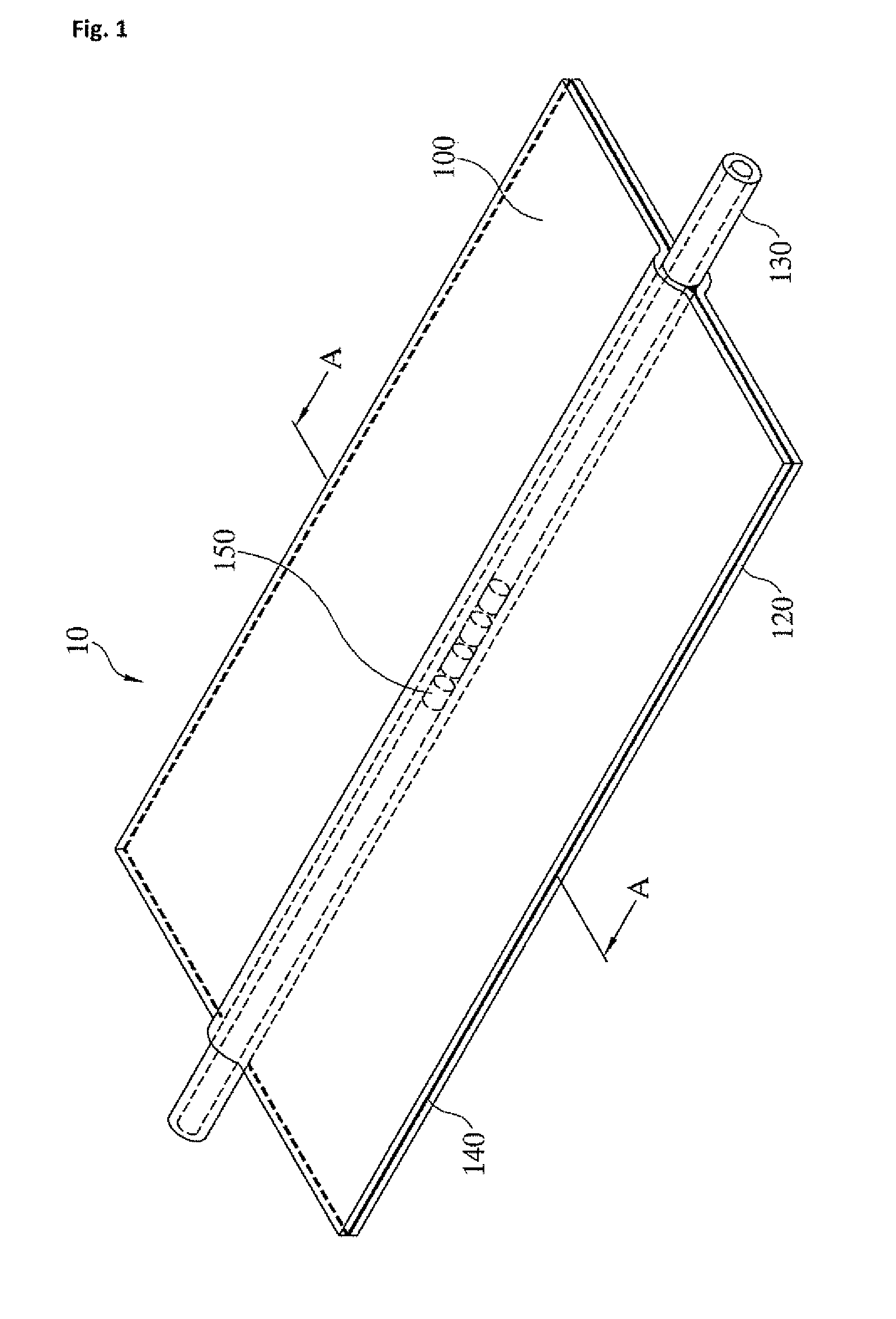
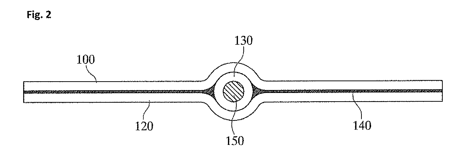
[0034]FIG. 1 is a perspective view of an FBG sensor 10 in accordance with the present invention, and FIG. 2 is a cross-sectional view of FIG. 1 in a direction A-A. As shown in FIGS. 1 and 2, an FBG sensor 150 is placed in the middle portion of an optical fiber 130. First and second metal foils 100 and 120 come in contact with the FBG sensor 150 up and down. The first and the second metal foils 100 and 120 and the optical fiber 130 are densely bonded together by an adhesive layer 140.

[0035]Each of the first and the second metal foils 100 and 120 may be an aluminum foil having a thickness ranging from 10 μm to 30 μm. More preferably, each of the first and the second metal foils 100 and 120 may have a thickness ranging from 15 μm to 20 W. If the thickness is less than 10 μm, the metal foil is torn when being handled or it is difficult to manufacture the metal foil. If the thickness is greater than 30 μm, it may be difficult to accurately measure the residual strain of the metal foil be...

second embodiment

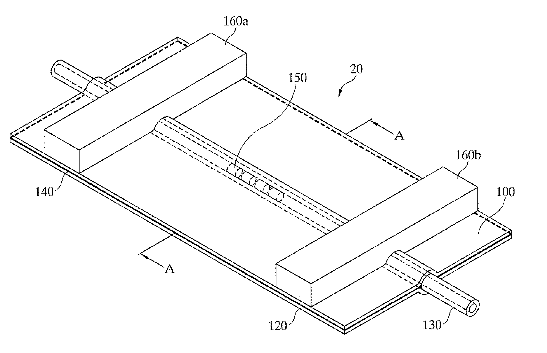
[0045]In addition, step for bonding the brackets 160a and 160b as in the second embodiment shown in FIG. 3 may be added, if necessary. The pair of brackets 160a and 160b is bonded at positions spaced apart from each other left and right about 2.5 cm on the basis of the center thereof using epoxy resin. The manufacturing method of the FBG sensor 10, 20 according to the present invention is completed through such steps.

[0046]

[0047]A use method for measuring a maximum strain using the first and the second embodiments is described in detail below with reference to the accompanying drawings. First, a sensitivity coefficient Csen between a maximum strain and a residual strain is defined as follows.

Csen=emaxeres[Equation1]

[0048]In Equation 1, emax is a maximum strain, and eres is a residual strain. Thereafter, after the FBG sensor according to the present invention and a strain gauge are attached to a specific sample, a tensile test is performed in a tensile tester. The sensitivity coeffic...


PUM

PropertyMeasurementUnit
thicknessaaaaaaaaaa
thicknessaaaaaaaaaa
thicknessaaaaaaaaaa

Abstract

The present invention relates to an FBG sensor for measuring a maximum strain of an object being measured, a method for manufacturing the sensor, and a method of using the sensor. To this end, provided is the FBG sensor for measuring a maximum strain, comprising: an optical fiber (130) having an FBG sensor (150) therein; a first metallic foil (120) contacting the optical fiber (130) on one surface thereof; a second metallic foil (120) which comes into surface-contact with the one surface; an adhesive layer (140) provided between the first and second metallic foils (100, 120); a means for measuring a residual strain of the first and second metallic foils (100, 120) through the FBG sensor (150); and a means for calculating a maximum strain on the basis of the measured residual strain and a sensitivity coefficient (Csen) obtained through experimentation.

Description

TECHNICAL FIELD[0001]The present invention relates to an FBG sensor and, more particularly, to an FBG sensor capable of measuring a maximum strain of the object to be measured, a method of manufacturing the sensor, and a method of using the sensor.BACKGROUND ART[0002]In general, a fiber Bragg grating (FBG) sensor refers to a sensor using the reflection, refraction, diffraction, and transmission phenomena of light by transmitting light through an optical fiber. In such an FBG sensor, ultraviolet rays are selectively radiated to a glass optical fiber so that a pattern whose refractive index is periodically changed finely is formed in the length direction of the optical fiber.[0003]Such an FBG sensor is characterized in that it has a low insertion loss because it can be formed as a filter within an optical fiber. Furthermore, the FBG sensor has a very low manufacturing cost in the case of mass production, and the bandwidth of the filter can be very small in size.[0004]Other characteris...

Claims


Application Information

Patent Timeline
Patent Type & Authority Applications(United States)
IPC IPC(8): G01L1/24G01B11/16
CPCG01B11/165G01L1/246G01B1/00G01B11/18G01D5/35316G01D5/3537G01B11/16G01M11/085G01L1/242G01N21/412G01M5/0033G01N21/8806G01K11/3206G01D5/353
Inventor KWON, IL-BUMIM, JOO EUNKIM, MI HYUNCHOI, KI SUN
Owner KOREA RES INST OF STANDARDS & SCI
Why Eureka
Try Eureka