Detecting clouds using polarized sunlight

a technology of polarized sunlight and clouds, applied in the field of meteorology and weather detection, can solve the problems of difficult to detect transparent super-thin clouds by satellite imagers, difficulty in detecting low water vapor in atmospheres, and inability to reliably use this method, etc., and achieve the effect of less expensive operation

Active Publication Date: 2016-07-28
UNITED STATES OF AMERICA THE AS REPRESENTED BY THE SEC OF THE ARMY
View PDF17 Cites 15 Cited by
  • Summary
  • Abstract
  • Description
  • Claims
  • Application Information

AI Technical Summary

Benefits of technology

[0017]Unlike lidar, which uses a laser light source, passive system embodiments can use natural light from the sun. Thus, only scattered sunligh

Problems solved by technology

Due to uncertainties in surface reflectance, transparent super-thin clouds generally cannot be detected by satellite imagers, like the MODIS and the Advanced Very High Resolution Radiometer that only measure the total radiance of the reflected solar light.
Using a strong water vapor absorption channel such as the 1.38 μm radiance to exclude the surface and low-layer effects can be effective on high cirrus, but may encounter difficulties for atmospheres with low water vapor.
The reliability of this method is also questionable if the clouds' optical depth is smaller than about 0.5, when their backscattered intensity is low.
The sensitivity of the 1.38 μm cha

Method used


Image

  • Detecting clouds using polarized sunlight
  • Detecting clouds using polarized sunlight
  • Detecting clouds using polarized sunlight

Examples


Embodiment Construction

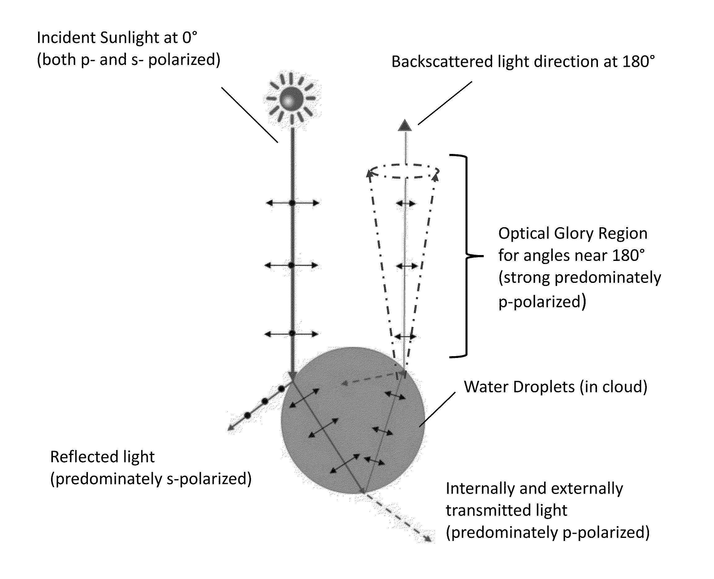
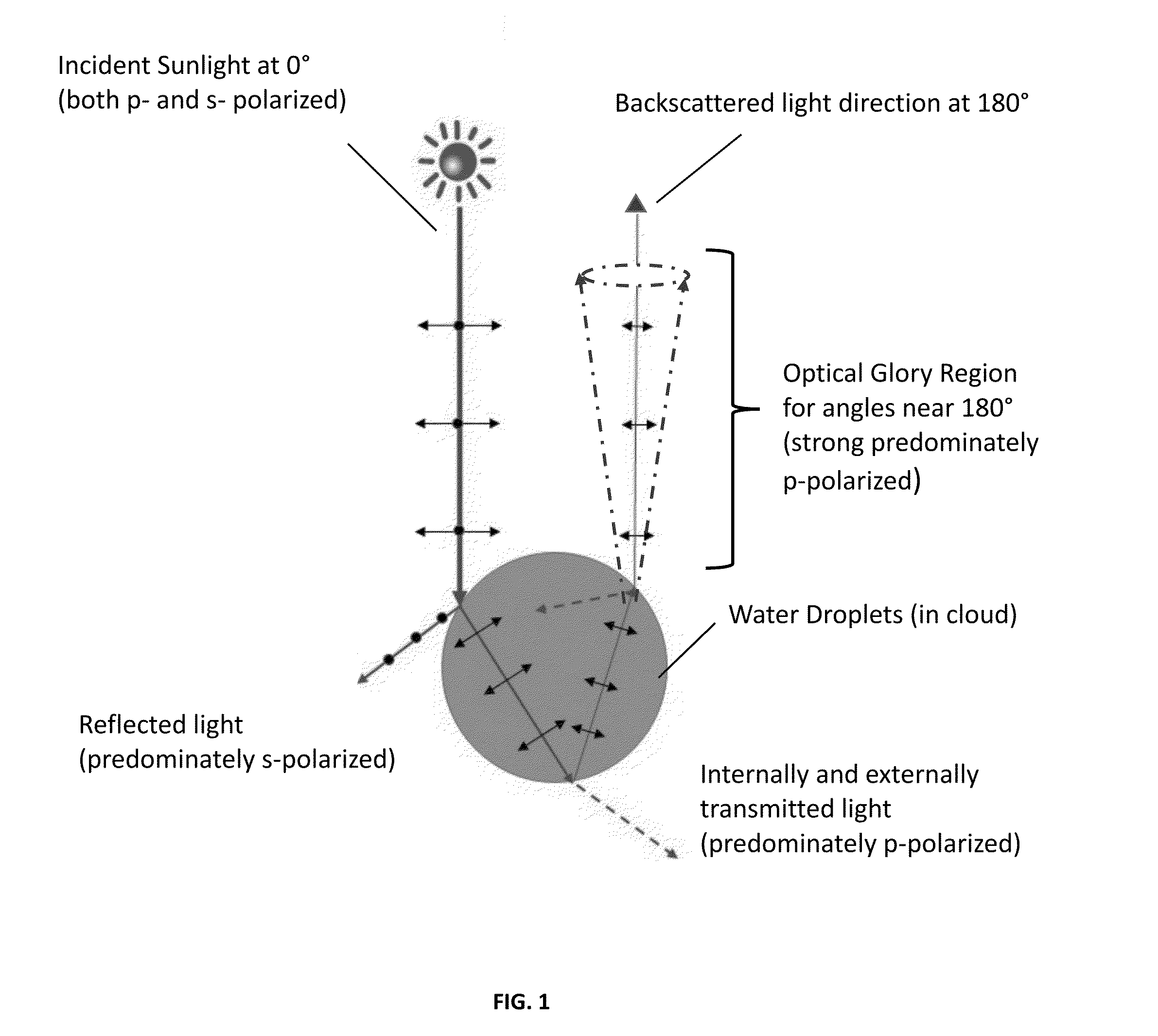
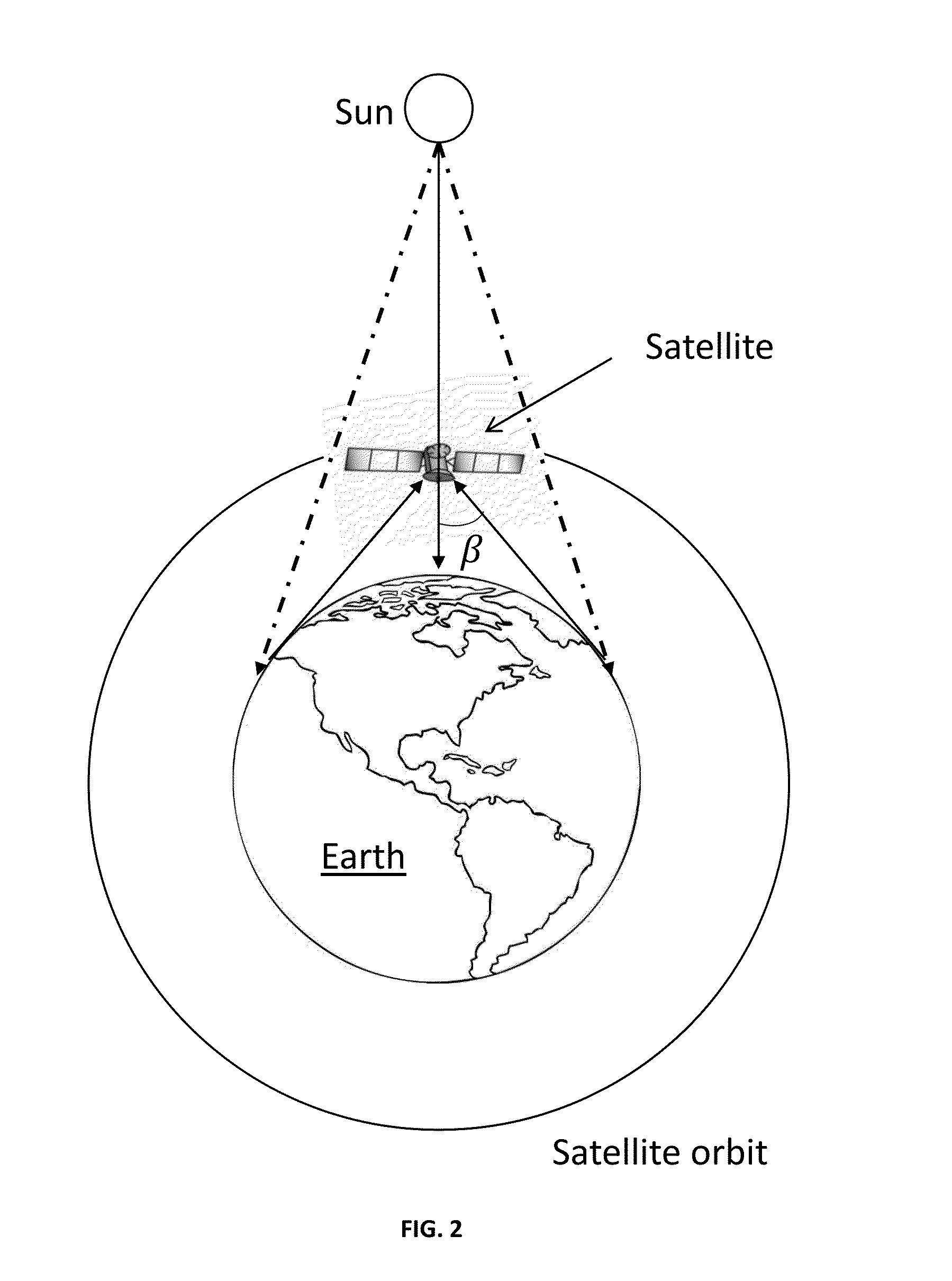
[0031]The inventors studied solar radiation backscattered from clouds with both satellite data and a radiative-transfer model. They have found that, while the dominant backscattered electric field from the clear-sky Earth-atmosphere system is nearly parallel to the Earth surface, when clouds are present, this electric field can rotate from the parallel to the perpendicular direction. And, more particularly, they identified that a distinct feature, i.e., characteristic of clouds, is responsible for this polarization change. This feature is the result of the optical phenomenon known as a glory. Results of this discovery and initial findings are reported in more detail in the article by W. Sun, G. Videen, and M. I. Mishchenko, titled “Detecting super-thin clouds with polarized sunlight.”Geophys. Res. Lett., 41, no. 2, 688-693 (2014), which was incorporated in and formed a basis of the aforementioned '662 provisional application. The inventors used data obtained from the PARASOL satelli...


PUM


Abstract

A novel methodology for detecting cloud particles is disclosed herein. This methodology exploits the optical glory phenomenon. According to one embodiment, a method for detecting clouds includes receiving data from a sensor which is configured to measure polarization of scattered light in a direction substantially opposite to the direction of incident light, and identifying, from the received sensor data, a cloud based on the polarization of the scattered light.

Description

CROSS REFERENCE TO RELATED APPLICATION(S)[0001]This application claims the benefit of U.S. Provisional Patent Application No. 62 / 107,662 filed Jan. 26, 2015, the disclosure of which is herein incorporated by reference in its entirety for all purposes.GOVERNMENT INTEREST[0002]The invention described herein may be manufactured, used and licensed by or for the U.S. Government without the payment of royalties thereon. Research underlying this invention was funded, in part, under NASA Glory fund 09-GLORY09-0027.BACKGROUND OF THE INVENTION[0003]1. Field[0004]Embodiments of the present invention generally relate to meteorology and weather detection, and more specifically, to detecting clouds using polarized sunlight.[0005]2. Description of Related Art[0006]Super-thin cirrus clouds with optical depths smaller than approximately 0.3 exist globally. These clouds are important to the radiation energy balance of the Earth. They also can affect the remote sensing of aerosols, surface temperature...

Claims


Application Information

Patent Timeline
IPC IPC(8): G01N21/21G01N21/49
CPCG01N21/21G01N21/49G01N2201/0616G01N2201/0683G01N2201/12G01N21/538G01N2021/4792G01W1/02
Inventor SUN, WENBOVIDEEN, GORDONMISHCHENKO, MICHAEL I.
Owner UNITED STATES OF AMERICA THE AS REPRESENTED BY THE SEC OF THE ARMY
Why Eureka
Try Eureka