Magnetic recording medium

a recording medium and magnetic technology, applied in the field of magnetic recording mediums, can solve the problems of reduced thermal stability of written magnetization (signal), difficult writing of magnetization (signal), and limitations on heating means that can be used, and achieve the effect of high heat stability of written magnetization

Active Publication Date: 2016-08-04
FUJI ELECTRIC CO LTD
View PDF2 Cites 8 Cited by
  • Summary
  • Abstract
  • Description
  • Claims
  • Application Information

AI Technical Summary

Benefits of technology

[0017]A magnetic recording medium containing a magnetic recording layer with a high magnetic anisotropy constant Ku, a large anisotropic magnetic field Hk, and a low Curie temperature can be obtained by using the constructions described above. The magnetic recording medium of the invention disclosed in the present specification makes it possible to write at lower heating temperatures in thermally-assisted recording methods. At the same time, the magnetic recording medium of the invention disclosed in the present specification can realize a high heat stability for the written magnetization (signal). Moreover, desired properties, e.g., a large saturation magnetization Ms for the magnetic recording layer as a whole, can be realized by combining the magnetic layer that contains the Ru-containing ordered alloy with a different type of magnetic layer.

Problems solved by technology

On the other hand, reducing the grain size of magnetic crystal grains causes a reduction in the thermal stability of the written magnetization (signal).
However, magnetic recording media that have a magnetic recording layer formed of a highly magnetically anisotropic material exhibit a high coercivity and the writing of magnetization (signal) is then made more difficult.
Due, however, to the various requirements imposed by the magnetic head, there are limitations on the heating means that can be used.
However, the current situation is that there has been little progress in research on Ru as a material added to ordered alloys.

Method used


Image

  • Magnetic recording medium
  • Magnetic recording medium
  • Magnetic recording medium

Examples


example 1

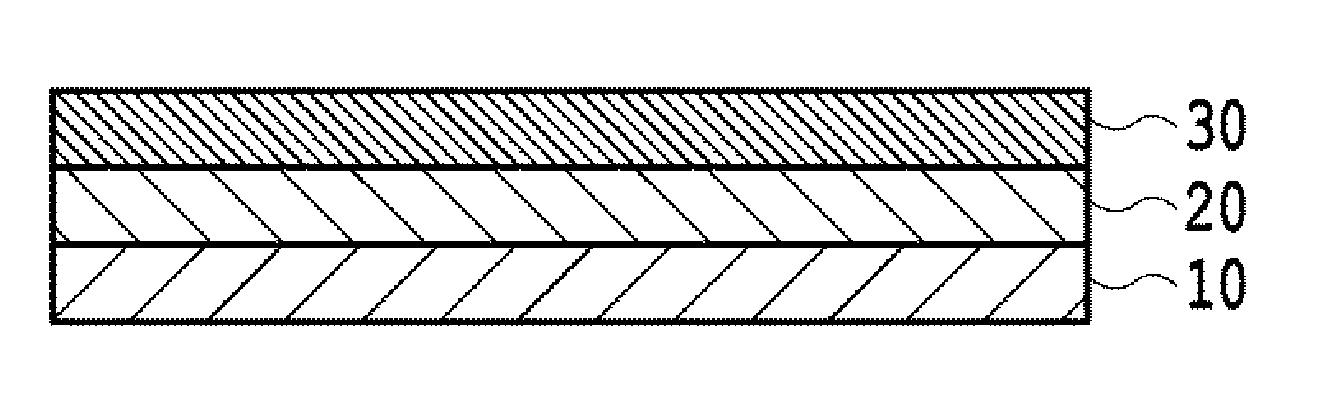
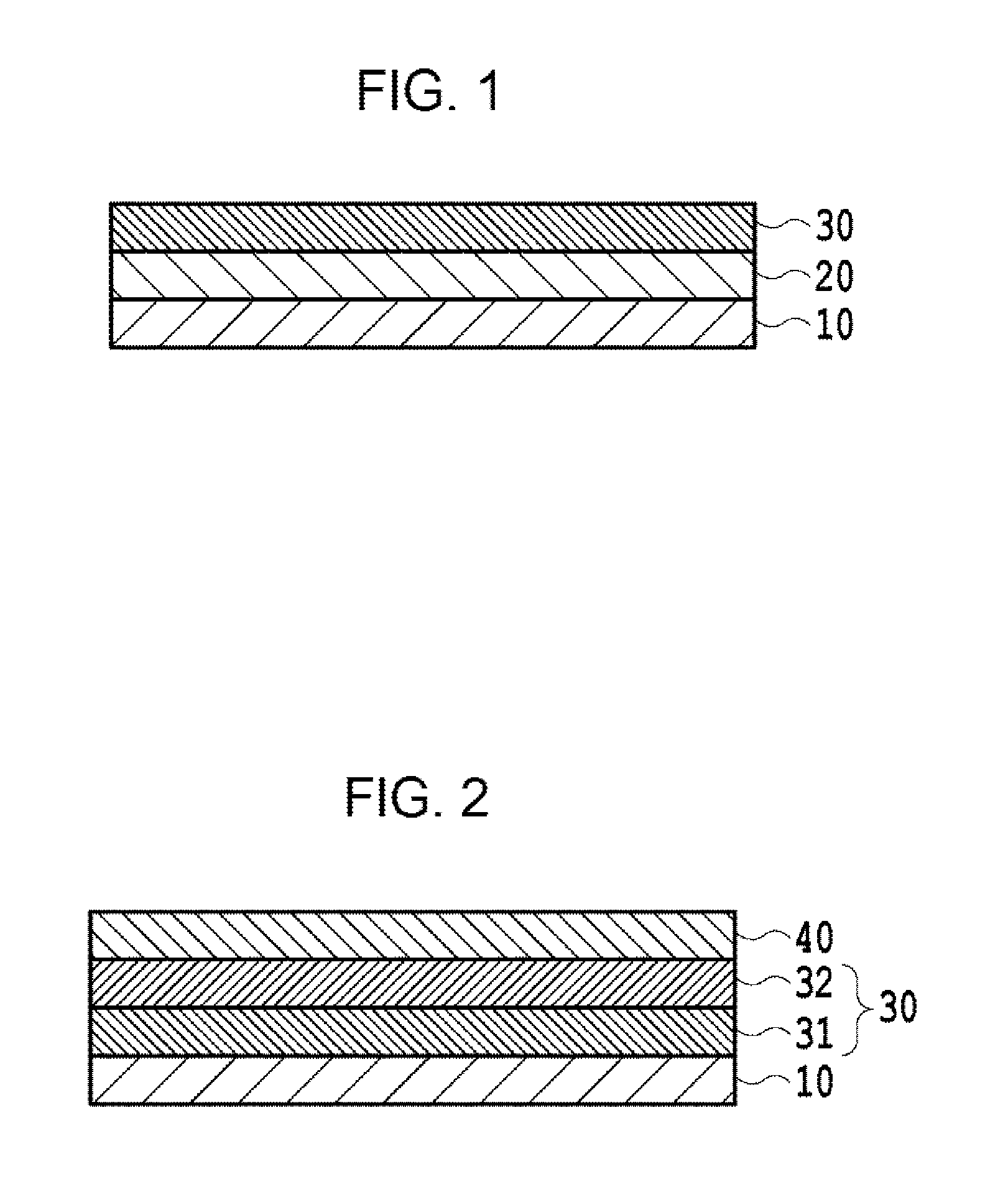
[0059]A nonmagnetic substrate 10 was prepared by cleaning a (001) MgO single-crystal substrate that had a smooth, flat surface. After cleaning, the nonmagnetic substrate 10 was introduced into a sputtering apparatus. After the nonmagnetic substrate 10 had been heated to 350° C., a Pt seed layer 20 with a film thickness of 20 nm was formed by RF magnetron sputtering in Ar gas at a pressure of 0.44 Pa using a Pt target.

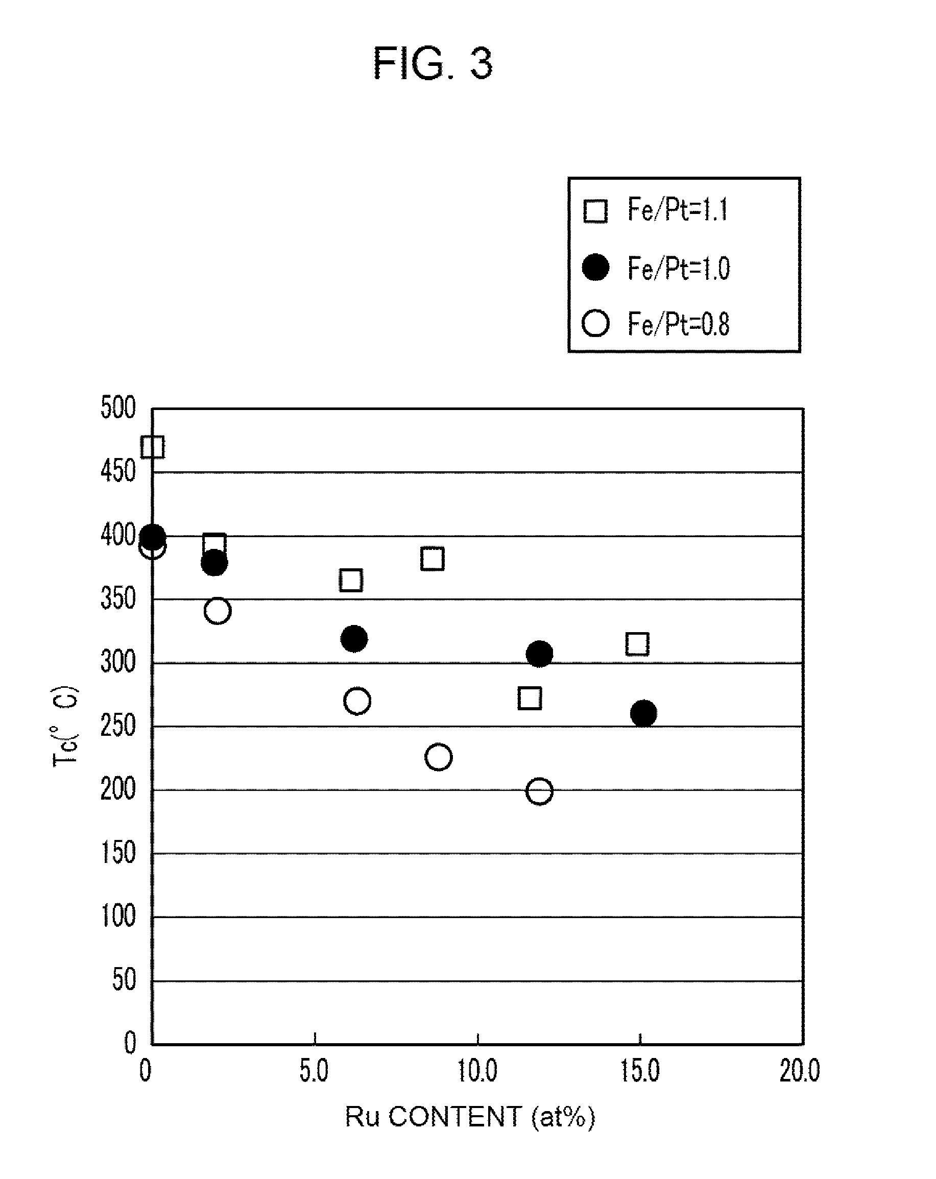
[0060]The nonmagnetic substrate 10 bearing the seed layer 20 was then heated to 350° C. and an FePtRu magnetic recording layer 30 with a film thickness of 10 nm was formed by RF magnetron sputtering in Ar gas at a pressure of 0.60 Pa using an FePt target and an Ru target, thus yielding a magnetic recording medium having the structure shown in FIG. 1. The Fe and Pt contents in the magnetic recording layer were adjusted using a target with an Fe / Pt ratio of 1.1, a target with an Fe / Pt ratio of 1.0, and a target with an Fe / Pt ratio of 0.8 for the FePt target. In addition, ...

example 2

[0070]A nonmagnetic substrate 10 was prepared by cleaning a (001) MgO single-crystal substrate that had a smooth, flat surface. After cleaning, the nonmagnetic substrate 10 was introduced into a sputtering apparatus.

[0071]After the nonmagnetic substrate 10 had been heated to 430° C., an FePt—C first magnetic layer 31 having a granular structure and a film thickness of 2 nm was formed by DC magnetron sputtering in Ar gas at a pressure of 1.5 Pa using an FePt target and a C target. The power applied to the FePt target was 40 W, and the power applied to the C target was 232 W. The Fe content and Pt content in the magnetic crystal grains in the resulting first magnetic layer 31 was 49 at % and 51 at %, respectively, with reference to the total number of atoms in the magnetic crystal grains. The content of the C constituting the nonmagnetic grain boundary was 40 volume % with reference to the volume of the first magnetic layer 31.

[0072]The nonmagnetic substrate 10 bearing the first magne...

example 3

[0076]Magnetic recording media were obtained by repeating the procedure in Example 2, but in this case changing the amount of Ru addition by adjusting the power applied to each of the targets during formation of the second magnetic layer 32. The contents of the Fe, Pt, and Ru in the magnetic crystal grains of the resulting second magnetic layers 32 of this example were 46 at %, 48 at %, and 6 at %, respectively, with reference to the total number of atoms in the magnetic crystal grains.

[0077]The saturation magnetization Ms and magnetic anisotropy constant Ku were measured on the obtained magnetic recording layers using the same procedures as in Example 2 and the net magnetic anisotropy constant Ku_grain was calculated for the magnetic crystal grains. The compositions of the magnetic recording layers and the results of the measurements are given in Table 5.


PUM

PropertyMeasurementUnit
temperatureaaaaaaaaaa
thicknessaaaaaaaaaa

Abstract

The present invention provides a magnetic recording layer that has a high magnetic anisotropy constant Ku and a low Curie temperature Tc, as well as a magnetic recording medium that incorporates such a magnetic recording layer. The magnetic recording medium of the present invention includes a nonmagnetic substrate and a magnetic recording layer containing an ordered alloy. The ordered alloy may contain at least one element selected from the group consisting of Fe and Ni; at least one element selected from the group consisting of Pt, Pd, Au, Rh and Ir; and Ru.

Description

CROSS-REFERENCE TO RELATED APPLICATIONS[0001]This non-provisional application for a U.S. patent is a Continuation of International Application PCT / JP2015 / 001426 filed Mar. 13, 2015, which claims priority from JP PA 2014-077114 filed Apr. 3, 2014, and from PCT / JP2014 / 005110 filed Oct. 24, 2014, the entire contents of all of which are hereby incorporated by reference.BACKGROUND OF THE INVENTION[0002]1. Field of the Invention[0003]The invention disclosed in the present specification relates to a magnetic recording medium. The invention disclosed in the present specification particularly relates to a magnetic recording medium for use in energy-assisted magnetic recording methods. The invention disclosed in the present specification more particularly relates to a magnetic recording medium for use in thermally-assisted magnetic recording methods.[0004]2. Background of the Related Art[0005]Perpendicular magnetic recording methods are used as a technique for realizing higher magnetic record...

Claims


Application Information

Patent Timeline
Patent Type & Authority Applications(United States)
IPC IPC(8): G11B5/65
CPCG11B5/65G11B5/653G11B5/66
Inventor MORIYA, TOMOHIRONAKATA, HITOSHIKIKUCHI, HIROTOKATAOKA, HIROYASUFURUTA, AKIRASHIMATSU, TAKEHITO
Owner FUJI ELECTRIC CO LTD
Why Eureka
Try Eureka