Metering device for delivery of a liquid or viscous substance

a technology for liquids and viscous substances, applied in the direction of liquid/fluent solid measurements, volume measurement, fluid delivery, etc., can solve the problems of costly parts replacement and production loss, cost and often not reliable, and deleterious effects

Inactive Publication Date: 2016-08-11
OPTIMOL TRIBOTECHN +2
View PDF6 Cites 0 Cited by
  • Summary
  • Abstract
  • Description
  • Claims
  • Application Information

AI Technical Summary

Benefits of technology

[0022]An advantage of the device is the reduction of the residual volume to a value close to zero. This is due to the particular layout of the device. Indeed, at end of the discharge stroke, both non-return valves arranged face to face are close to each other and can even substantially contact each other in some embodiments of the invention. In some embodiments, means can however be placed to prevent a direct contact between the two valves. Since in the device according to the invention, the residual volume corresponds to the space between these valves, it is

Problems solved by technology

In many cases, machines and apparatuses, even nowadays, are lubricated manually which is costly and often not reliable.
Lack of correct lubrication is the cause of costly parts replacement and production loss.
The constant high pressure applied to the reservoir in this type of systems has a deleterious effect when the lubricant is grease.
In the particular case of greases, high pressure can cause separation of oil from the thickener or soap.
This phenomenon can lead to clogging of the system, failure and high replacement cost.
Initial investment can be high and maintenance is complex.
This non-negligible residual volume is deleterious for the volumetric efficiency of the pump, which is the ratio between the actual volume of lubricant expelled at every pumping cycle and the volumetric capacity of the pump.
From a practical point of view, the existence of a non-negligible residual volume implies that it is impossible to create a high level vacuum in the intermediate chamber.
This is especially a problem when the residual volume is at least par

Method used


Image

  • Metering device for delivery of a liquid or viscous substance
  • Metering device for delivery of a liquid or viscous substance
  • Metering device for delivery of a liquid or viscous substance

Examples


Embodiment Construction

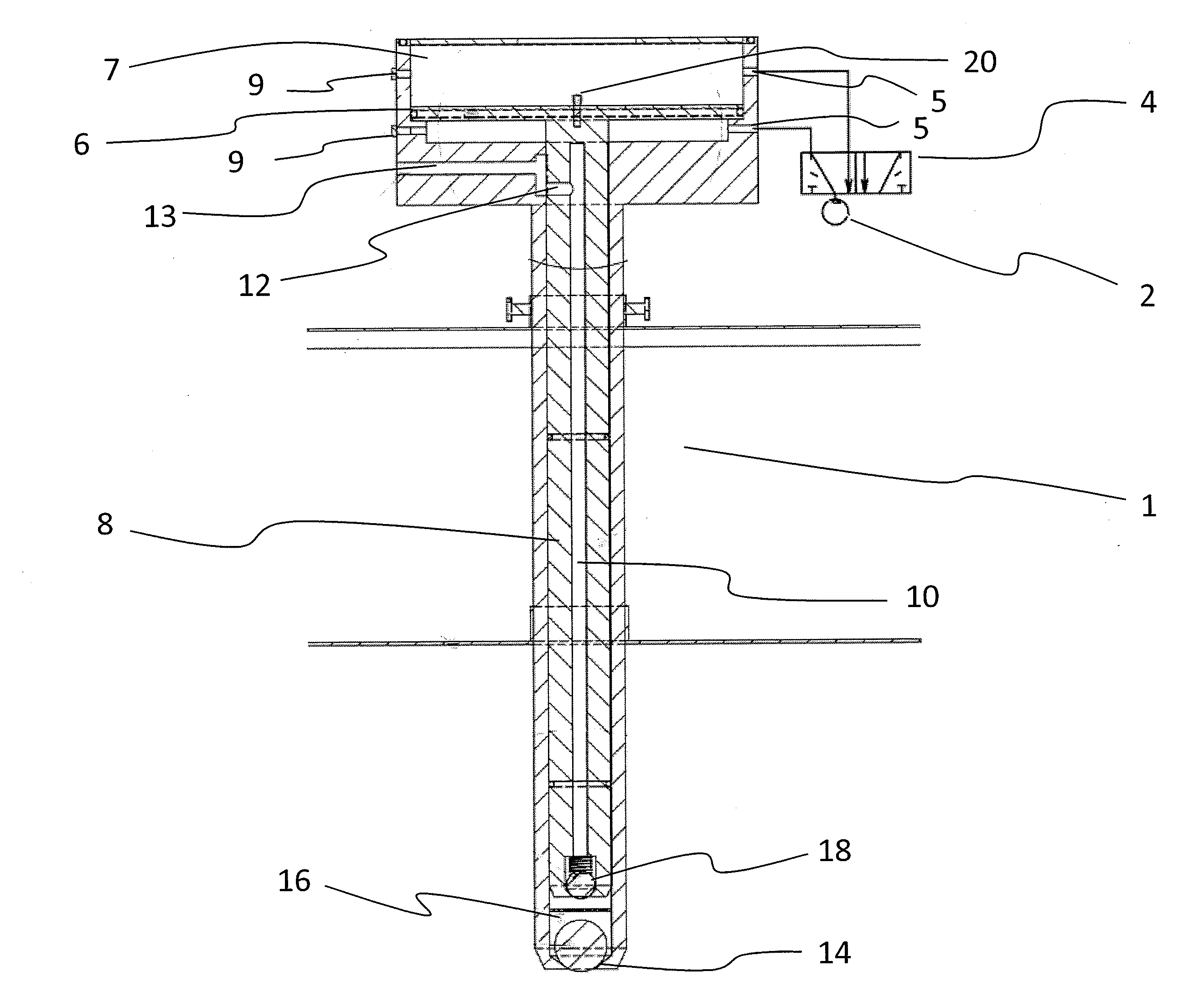
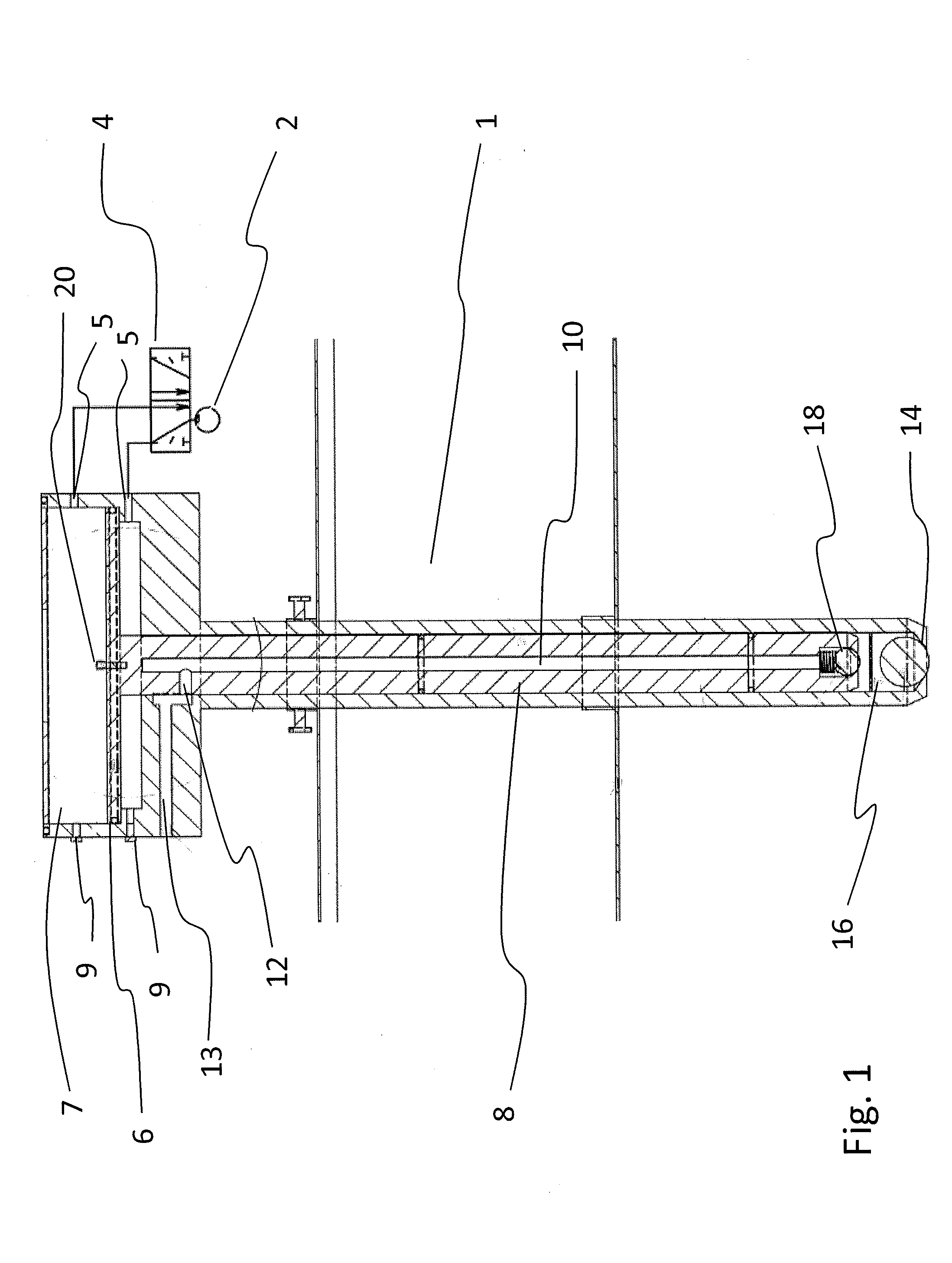
[0031]The device of FIG. 1 consists of a casing 1 supplied with compressed air. A timer 2 activates a standard electro-pneumatic valve 4 to alternatively supply air under pressure through air inlets 5 to the upper or lower surface of the largest cross-section of the piston 6. The piston cross-section 6 is slidably mounted in a pneumatic chamber 7, and divides the pneumatic chamber into two sub chambers, each sub chamber being sealingly insulated from the other by said larger cross-section, each sub chamber being provided with an air inlet 5 and an air outlet 9, for receiving an actuating force of compressed air allowing to vary the position of said piston larger cross-section in said pneumatic chamber, said outlets 9 being present in order to allow a series connection of several devices supplied with the same compressed air source. When only one device is used, outlets 9 have to be plugged.

[0032]The piston larger cross-section 6 is mounted on a piston rod 8 having a central bore 10....


PUM


Abstract

A device for metered delivery of a liquid or viscous substance comprising a casing, a reciprocating differential piston able to slide in said casing, a metering chamber and at least one outlet for media delivery, the volume of the metering chamber varying during the piston stroke and comprising an inlet communicating with the outside of the casing via a first non-return valve, said piston comprising a central bore connecting said metering chamber by way of a central bore inlet and said at least one outlet via a passage, said central bore inlet being provided with a second non-return valve, said first non-return valve and second non-return valve being arranged face to face, piston stroke length being able to adjust the volume of the metering chamber.

Description

FIELD OF THE INVENTION[0001]The invention relates to a device for metered delivery of a liquid or viscous substance, especially a lubricant needing to be delivered to points of machines or apparatuses.DESCRIPTION OF PRIOR ART[0002]Machines and apparatuses have numerous points needing lubrication with oils or greases or both in accordance with a predetermined lubrication plan. In many cases, machines and apparatuses, even nowadays, are lubricated manually which is costly and often not reliable. Lack of correct lubrication is the cause of costly parts replacement and production loss. However, machines and apparatuses are increasingly equipped with central automatic lubrication systems. Several devices for automatic lubrication are described in the prior art.[0003]EP0120522 provides a pneumatically operated pump with a pressurised reservoir for grease lubrication systems. The constant high pressure applied to the reservoir in this type of systems has a deleterious effect when the lubri...

Claims


Application Information

Patent Timeline
IPC IPC(8): G01F13/00F04B19/22F04B53/18F04B53/16F04B23/02G01F15/00F04B53/12
CPCF04B9/125F04B13/00F04B15/02F04B53/126G01F15/005F04B23/02F04B53/16F04B53/18G01F13/00F04B19/22
Inventor VAN DAMME, ERICLUANG-RAJ, AMATHITH
Owner OPTIMOL TRIBOTECHN
Why Eureka
Try Eureka