Substrate treatment method and substrate treatment equipment

a substrate treatment and equipment technology, applied in the direction of inorganic non-surface active detergent compositions, multi-stage water/sewage treatment, cleaning using liquids, etc., can solve the problem of deterioration of the performance of the integrated circuit device that is to be created from the substrate, increase the contact resistance, and block the precise control of the film thickness and the film quality of the gate oxide film. , to achieve the effect of suppressing or preventing the increase of the concentration of oxygen in the solution in

Active Publication Date: 2016-08-11
ORGANO CORP
View PDF4 Cites 20 Cited by
  • Summary
  • Abstract
  • Description
  • Claims
  • Application Information

AI Technical Summary

Benefits of technology

[0030]According to the disclosure, the hydrogen-dissolved treatment solution obtained by passing the hydrogen-dissolved solution (the concentration of dissolved hydrogen is 8 μg / L or higher) through the platinum-group metal catalyst disposed near the treatment chamber or in the treatment chamber is supplied into the treatment chamber and the treatment chamber is filled with the inert gas. Thereby, it is possible to treat a substrate to be treated by using the hydrogen-dissolved treatment solution of which the concentrations of oxygen and hydrogen peroxide are reduced to a predetermined value or less (the concentration of dissolved oxygen is 2 μg / L or less, the concentration of hydrogen peroxide is 2 μg / L or less), in the treatment chamber in which the concentration of oxygen gas on a surface of the substrate to be treated is reduced to a predetermined value (2%) or less. Therefore, it is possible to further suppress corrosion (oxidation or elution of metal) of a wiring exposed on the surface of the substrate to be treated, as compared to the substrate treatment equipment of the related art.
[0032]In the treatment chamber in which the concentration of oxygen gas on the surface of the substrate to be treated is reduced to the predetermined value (2%) or less, the hydrogen-dissolved treatment solution or the dilute chemical solution can be provided to the substrate. Therefore, it is possible to suppress or prevent the concentration of oxygen in the chemical solution from increasing due to the contact of the hydrogen-dissolved treatment solution or the dilute chemical solution with the air in the treatment chamber. That is, while maintaining the reduced state of the concentration of oxygen, it is possible to provide the hydrogen-dissolved treatment solution or the dilute chemical solution to the substrate.
[0033]According to the other aspect, a shield member having a surface facing the substrate is provided to shield an atmosphere of the substrate surface from a surrounding atmosphere. Thereby, it is possible to further suppress or prevent the concentration of oxygen in the atmosphere of the substrate surface from increasing. In this case, it is also possible to suppress a using amount of the inert gas.
[0037]According to another aspect, the inert gas is supplied to a tank configured to store therein the chemical solution or the above-mentioned tank for dilution, so that it is possible to suppress or prevent the concentration of oxygen in a solution in the tank from increasing. Therefore, it is possible to suppress or prevent the dilute chemical solution of which the concentration of oxygen has increased from being supplied into the treatment chamber.
[0038]In addition, a pipe to be coupled to the treatment chamber has a structure including an inner pipe through which a solution passes and an outer pipe configured to surround the inner pipe, and the inert gas is supplied to a space between the inner pipe and the outer pipe, so that it is possible to surround the inner pipe by the inert gas. Therefore, even when the inner pipe is formed of an oxygen permeable material such as a fluorine resin, for example, it is possible to reduce an amount of the oxygen to be introduced into the inner pipe via the inner pipe. Thereby, it is possible to suppress or prevent the oxygen from being dissolved in the solution flowing in the inner pipe to increase the concentration of oxygen in the solution. The outer pipe may be formed of PVC or a fluorine resin, for example.
[0039]As described above, according to the respective aspects of the disclosure, it is possible to further suppress the wiring exposed on the substrate surface from being corroded by the substrate treatment solution, as compared to the related art. Therefore, it is possible to provide the treatment technology of the substrate, which is difficult to deteriorate the performance of a manufactured integrated circuit device.

Problems solved by technology

This may block precise control of a film thickness and a film quality of a gate oxide film, or increase a contact resistance of a contact hole, a via, a plug, or the like.
Also in this case, the metal film (copper film, tungsten film or the like) on the substrate is oxidized by the dissolved oxygen in the polymer removal solution, thereby causing deterioration in the performance of the integrated circuit device that is to be created from the substrate.

Method used


Image

  • Substrate treatment method and substrate treatment equipment
  • Substrate treatment method and substrate treatment equipment
  • Substrate treatment method and substrate treatment equipment

Examples


first embodiment

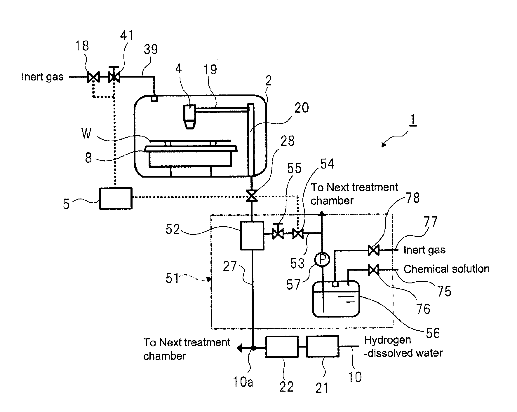
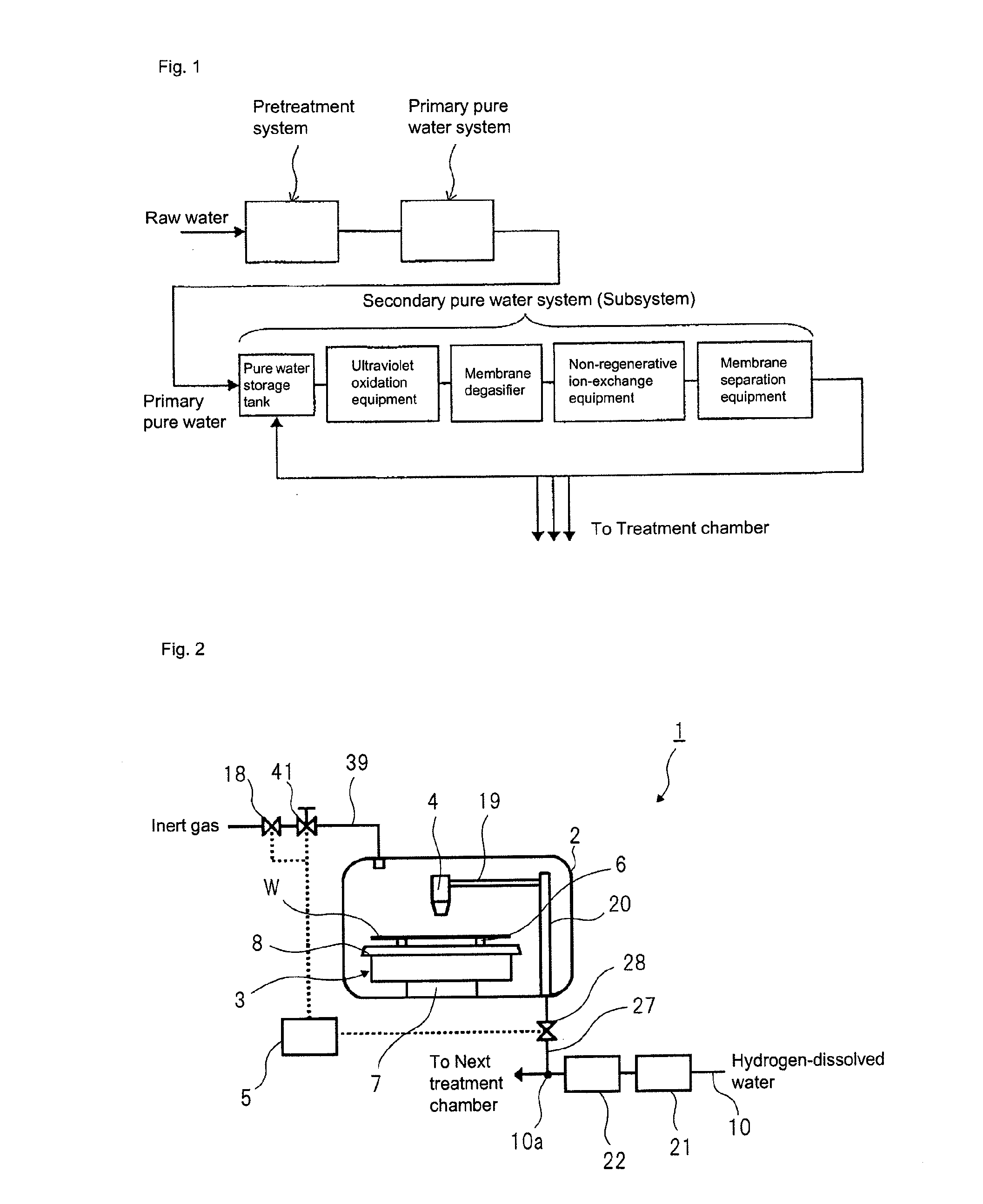
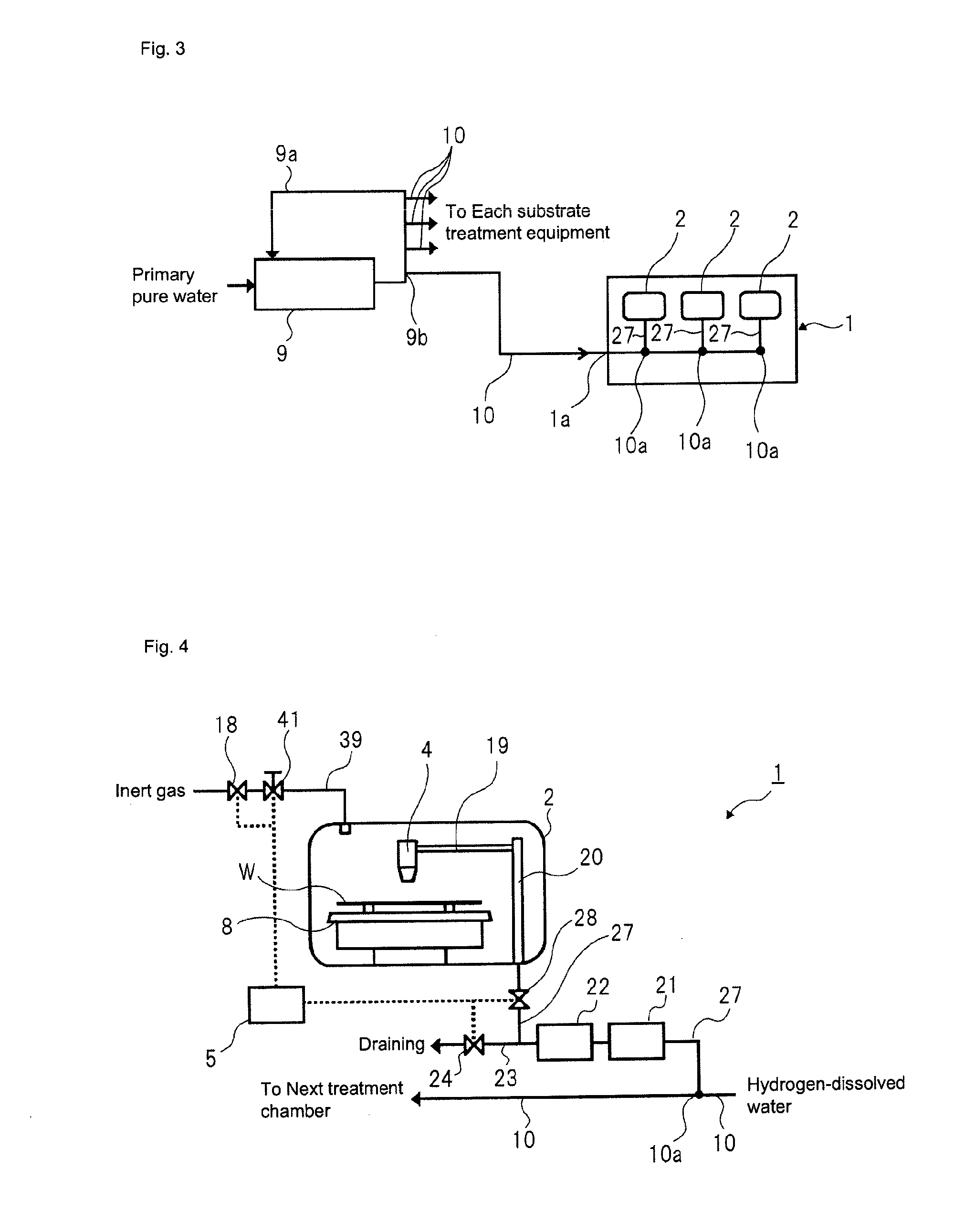
[0142]FIG. 2 depicts a schematic configuration of a substrate treatment equipment according to a first embodiment. A substrate treatment equipment 1 of the first embodiment is a single wafer treatment equipment configured to treat a substrate W one by one. In the first embodiment, the substrate W is a circular substrate, like a semiconductor wafer.

[0143]Referring to FIG. 2, the substrate treatment equipment 1 has one or more treatment chambers 2 partitioned by a partition wall. In each treatment chamber 2, a spin chuck 3 (a substrate holding mechanism, a substrate holding and rotating mechanism) configured to horizontally hold and rotate one substrate W, and a treatment solution nozzle 4 configured to supply a treatment solution to an upper surface of the substrate W held on the spin chuck 3 are provided.

[0144]The spin chuck 3 has a disc-shaped spin base 8 (holding base) horizontally attached to an upper end of a rotating shaft extending vertically, a plurality of sandwiching member...

second embodiment

[0221]The treatment chamber 2 of the first embodiment has the single wafer cleaning mechanism. However, the treatment chamber that is to be used for the disclosure is not limited thereto, and may be a treatment chamber having a batch-type cleaning mechanism.

[0222]FIG. 10 depicts an example where the treatment chamber of the aspect of FIG. 5 (the second modified aspect) is changed with a treatment chamber having a batch-type cleaning mechanism. FIG. 10 simply depicts an example, and not only the second modified aspect but also the first to sixth modified aspects can be applied to the treatment chamber 2 having the batch-type cleaning mechanism. In the meantime, the same constitutional elements as the first embodiment are denoted with the same reference numerals and the descriptions thereof are omitted.

[0223]Referring to FIG. 10, the treatment chamber 2 of the substrate treatment equipment 1 according to the second embodiment has a treatment tank 201 configured to store therein the tr...

third embodiment

[0233]FIG. 11 depicts a schematic configuration of a substrate treatment equipment according to a third embodiment of the disclosure.

[0234]In this embodiment, dilute hydrofluoric acid is prepared by mixing hydrofluoric acid (HF) and ultrapure water for cleaning or etching a semiconductor wafer, and is then supplied to the treatment chamber 2 of the substrate treatment equipment 1. In the description, ‘hydrofluoric acid’ may also be abbreviated as ‘HF.’ Also, in the disclosure, buffered hydrofluoric acid (BHF), which is to be mainly used for cleaning or etching an insulating film, may also be used in place of hydrofluoric acid (HF) of the treatment solution stock solution. The buffered hydrofluoric acid is a mixed solution of hydrofluoric acid (HF) and ammonium fluoride.

[0235]In this embodiment, the substrate treatment equipment 1 has a mixed water storage tank 300 configured to prepare and store therein dilute hydrofluoric acid (DHF) by mixing HF and ultrapure water, an HF supply li...


PUM


Abstract

Provided are a substrate treatment method and a substrate treatment equipment enabling greater suppression of corrosion or oxidation of metal wiring exposed on a substrate surface. The present invention relates to a substrate treatment equipment having a treatment chamber wherein a substrate is disposed, and whereto a substrate treatment solution for treating the substrate is supplied. This equipment is provided with an inert gas filling mechanism for filling with an inert gas the interior of the treatment chamber wherein the substrate is disposed, and, near or inside the treatment chamber, a catalytic unit filled with a platinum-group metal catalyst wherethrough a hydrogen-dissolved water including hydrogen added to ultra-pure water is passed. Obtained by passing the hydrogen-dissolved water through the platinum-group metal catalyst, a hydrogen-dissolved treatment solution is supplied as the substrate treatment solution into the treatment chamber by the equipment.

Description

TECHNICAL FIELD[0001]The disclosure relates to a substrate treatment method and a substrate treatment equipment for treating a substrate. More particularly, the disclosure relates to a substrate treatment method and a substrate treatment equipment to be used for cleaning treatment, chemical treatment or immersion treatment of a circuit substrate. The substrates to be treated include, for example, a semiconductor wafer, a substrate for a liquid crystal display device, a substrate for a plasma display, a substrate for a field emission display, a substrate for an optical disk, a substrate for a magnetic disk, a substrate for a magneto-optical disk, a substrate for a photomask, and a ceramic substrate.BACKGROUND ART[0002]Market demand exists for semiconductor integrated circuit devices having higher integration and higher speed. In order to meet this demand, lower-resistance copper wiring has been used in place of conventionally-used aluminum wiring. By combining the copper wiring with ...

Claims


Application Information

Patent Timeline
Patent Type & Authority Applications(United States)
IPC IPC(8): H01L21/02B08B3/08C02F9/00C02F1/68C23F1/16C02F1/20C02F1/70B01J19/24C11D7/08H01L21/67C02F1/44
CPCH01L21/02068C02F2305/00H01L21/67086H01L21/67017B08B3/08C02F9/00C02F1/68C02F1/444C02F1/442C02F1/20C02F1/705B01J19/24C11D7/08C23F1/16C02F2101/10C02F2103/04C02F2303/08H01L21/67051H01L21/02071C23G1/24C23G5/00H01L21/6708
Inventor YANO, DAISAKUYAMASHITA, YUKINARIMURAYAMA, MASAMIYAMANAKA, KOJI
Owner ORGANO CORP
Why Eureka
Try Eureka