
Atomic-layer deposition substrate

a technology of atomic layers and substrates, applied in the direction of chemical vapor deposition coatings, coatings, metallic material coating processes, etc., can solve the problems of substrate defect levels, difficult substrate processing, and unacceptable substrate processing, so as to prevent unwanted reactions on the chamber surface, the effect of fast and uniform gas over the substra

Inactive Publication Date: 2016-08-18
EASTMAN KODAK CO
View PDF3 Cites 32 Cited by
  • Summary
  • Abstract
  • Description
  • Claims
  • Application Information

AI Technical Summary

Benefits of technology

The patent describes a method for improving the stability of a moveable substrate during pneumatic levitation. A levitation stabilizing structure is used on the moveable substrate surface to harness the energy of the fluid flow and convert it into directional forces to control and minimize lateral movement of the substrate. The structure includes fluid collimating conduits, nozzles, bores, orifices, and other features that impinge on the surface of the stationary support. The use of the stabilizing structure does not require a planar substrate and can be used with both gas and liquid fluids. The technical effect is improved stability of the moveable substrate during pneumatic levitation.

Problems solved by technology

Processing of substrates may be more complicated, involving steps associated with changing the functionality of the material layer substantially by modifying the chemical composition of the surface of the substrate material layer or the material layer of the substrate itself.
There are many factors that can prevent acceptable substrate processing by introducing substrate defects.
Two factors contributing to substrate defect levels after processing are particle contamination and substrate physical contact.
Both particle contamination of the substrate surface and physical contact with either the substrate material layer or the substrate surface can lead to unacceptable substrate defects, some of which are manifest as defects in the uniformity of the surface properties of the substrate after processing.
This is surprising because the problems associated with the handling, manipulation, and fluid transport of chemically reactive materials is well known.
Some of these problems are 1) corrosion and dissolution of the materials of construction employed for the pumps, gauges, valves, tubing, and connections in the fluid delivery system leading to equipment failure and 2) deposit build-up at various locations in the fluid system from unintended side reactions of reactive species in the fluid with the materials of construction of the fluid delivery system which can lead to changes in the fluid flow and fluid pressure during fluid delivery system operation.
Furthermore, the physical positions of substrates that are subject to fluidic levitation tend to be unstable and the substrate position is mechanically controlled.
This mechanical control can induce particulate contamination or damage to the substrate.
However, U.S. Pat. No. 3,627,590 does not teach or disclose a method or apparatus to control and manage the reactivity of the fluid flow as it comes in contact with different surfaces of the fluid delivery system and associated equipment.
. . nearly impossible to center the exit orifice for the pressurized fluid over the support . . . . As a result, there is a force component tending to laterally shift the slice relative to the reference surface”.
In other words, the lateral motion of the substrate slice moves the substrate away from the pressurized fluid emitting from the reference surface resulting in a failure of the sample to float on the gas layer.
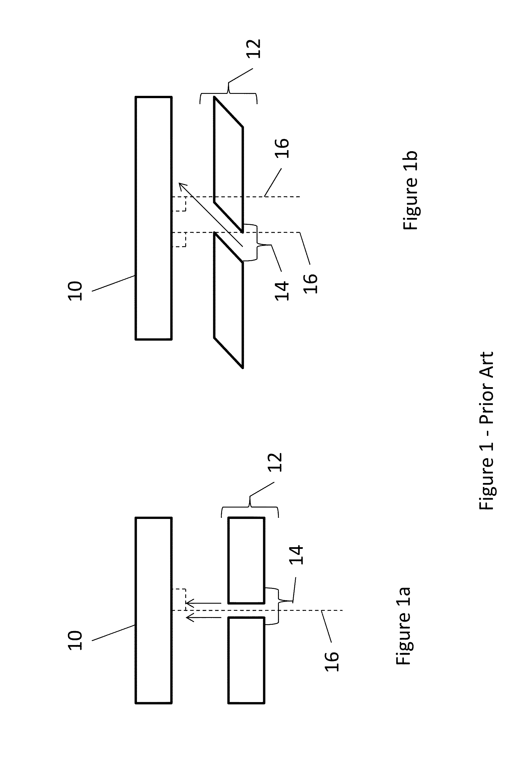
The problem identified by Mammel in U.S. Pat. No. 3,466,079 is one of uncontrollable lateral motion of the substrate during fluidic levitation because of the difficulty associated with positioning the substrate in the proper position over the pressurized fluid region.
This method of substrate handling differs from that described in U.S. Pat. No. 3,627,590 but possesses a commonality in the difficulty of maintaining the sample position during processing due to the frictionless nature of the gaseous floatation layer which enables non-contact processing.
The fluid-delivery system employed for fluidic levitation of a substrate and substrate processing disclosed in this art does not teach or disclose a method or apparatus to control and manage the reactivity of the fluid flow as it comes in contact with different surfaces of the fluid delivery system and associated equipment.
The mechanical instability of the device described in U.S. Publication No. 20080122151A1 makes it difficult to see how the device can achieve fluidic levitation of a substrate body on the porous gas emanating surface and keep the substrate body in a stable position with little or no lateral movement.
U.S. Pat. No. 6,805,749B2 mentions that the problem of “supplying process gas at elevated temperature and more particularly when depositing layers is that the apparatus used to supply the process gas becomes contaminated by deposition of the material concerned from the process gas.
This means that apparatuses of this type have to be cleaned regularly and that major problems arise with regard to clogging.” [Col 3, lines 9-17] This problem is managed in U.S. Pat. No. 6,805,749B2 by operating the apparatus in a temperature region where minimal deposition can occur whilst not eliminating the problem.
U.S. Pat. No. 6,805,749 B2 does not describe “the correct gas stream” and the specification of the document is insufficient to determine exactly what apparatus was employed to achieve the reported result.
Although the apparatus and method in U.S. Pat. No. 5,370,709 attempts to control the reactivity of the fluid flow by controlling the temperature of the fluid flow it is difficult to see how unintended deposition of the reactive precursor would not occur in the orifice itself during the semiconductor wafer processing operation since the orifice region is heated, also.
With continued deposition in the heated vapor delivery orifice during equipment operation, the orifice will eventually block, resulting in equipment failure as the diameter of the orifice decreases with increasing deposition.
The initial “parallel plate” configuration disclosed in FIG. 1 of U.S. Pat. No. 5,370,709 has no physical restraints for lateral movement of the substrate during levitation and by virtue of its similarity with the apparatus described in U.S. Pat. No. 3,466,079 would suffer from the same problem of positional stability and lateral movement of the substrate during operation thereby resulting in a useless apparatus.
U.S. Pat. No. 5,492,566 does not disclose a non-contact method for stabilizing the position during pneumatic levitation.
U.S. Pat. No. 6,601,888 B2 acknowledges that “preventing lateral movement of objects” that are levitated is a problem but does not provide any teaching or inventive disclosure concerning how to address this problem other than to mention the previously disclosed teaching in the art of fluidic levitation concerning the use of physical stops and barriers to prevent substrate motion.
The apparatus described appears complex, requiring control of fluid through multiple fluid ports with complicated electrical feedback circuits being required.
Such schemes are difficult to implement, can lead to levitation height instability and positional oscillation as a result of unstable fluid flows, and require complicated pneumatic control sequences and feedback control loops for execution.
U.S. Pat. No. 5,470,420 does not teach pneumatic levitation of a moveable substrate using both tilted jets and orthogonal jets simultaneously.
The pneumatic levitation produced by the apparatus in U.S. Pat. Nos. 5,492,566 and 5,967,578 is unstable with respect to lateral movement of the opposing substrate for the reasons cited in U.S. Pat. No. 3,466,079 because it is nearly impossible to center the centroid of the moveable substrate over the centroid of the annular nozzle structure.
When sufficient fluidic pressure is applied to produce an orthogonal jet of sufficient pressure and velocity, the moveable substrate 10 is fluidically levitated but is unstable with respect to lateral motion of the substrate.
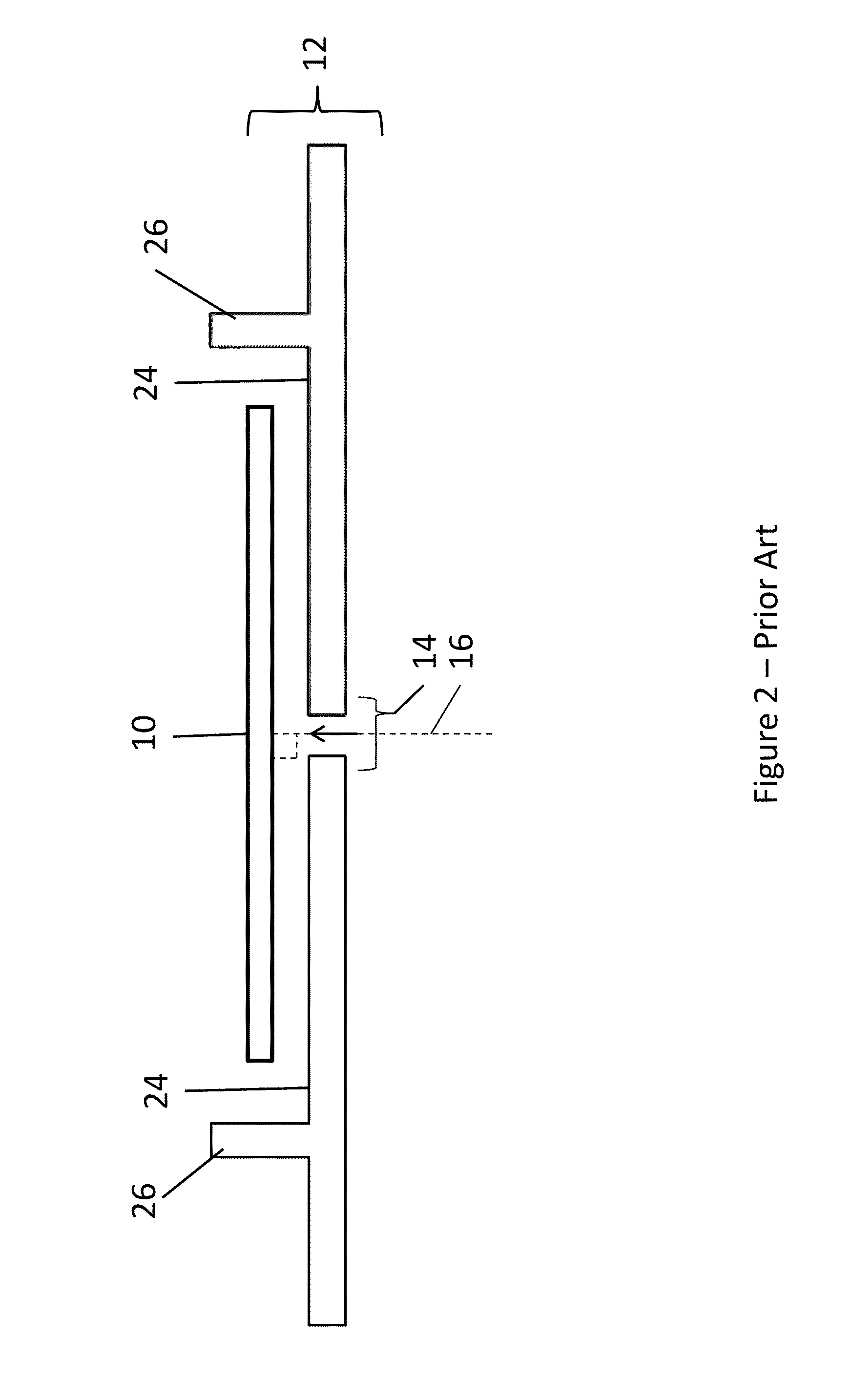
The presence of reactive chemical substances in the fluid flow during fluidic levitation can cause complication with equipment operation.
In particular, the presence of reactive reagents in the orthogonal jet can cause complications with equipment operation.
If the fluid delivery system surfaces are chemically reactive with the fluid flow then elements of the fluid delivery system whose critical dimensions must be maintained for robust system operation may change over time becoming larger, smaller, or even failing altogether.
However, the provision and removal of gases in a vacuum typically requires pumping the gases into and out of the vacuum chamber.
This process can take seconds, or even minutes.

Method used


Image

  • Atomic-layer deposition substrate
  • Atomic-layer deposition substrate
  • Atomic-layer deposition substrate

Examples


examples 1-14

Pneumatic Levitation with and without Levitation Stabilizing Structures

[0229]The purpose of the following examples is to demonstrate the effectiveness of levitation stabilizing structures for improving the positional stability of pneumatically levitated moveable substrates. Recalling that all prior art employed physical stops on the gas-emanating stationary support in order to prevent undesirable moveable substrate motion that would cause failure of pneumatic levitation, note that examples 1-14 were carried out in the absence of any physical stops being present on the gas-emanating stationary support that could impede moveable substrate motion. In other words, since the motion of the moveable substrate was completely unimpeded during pneumatic levitation, failure of the sample to remain in a stable position during pneumatic levitation could be easily detected, thereby enabling a simple determination of moveable substrate configurations which are positionally stable during pneumatic ...

example 1

[0232]2000 Å of thermal oxide was grown on a 675 micron thick, 150 mm diameter silicon wafer with a flat to indicate wafer orientation. The surface of wafer was completely featureless and planar. The wafer of example 1 was mounted on the stationary gas emitting support and an attempt was made to pneumatically levitate the moveable substrate at orthogonal jet manifold pressures between 10 and 35 psig. Although the wafer substrate levitated, the pneumatic levitation was not positionally stable and exhibited excessive, rapidly developing lateral motion. The moveable substrate of example 1 rapidly slid off the surface of the stationary gas emitting support: it did not remain in stationary during pneumatic levitation. Example 1 failed pneumatic levitation testing due to insufficient positional stability during levitation.

example 2

[0233]A levitation stabilizing structure consisting of an annulus having 100 mm inside diameter, 102 mm outside diameter, and a height of approximately 200 microns was fabricated on the surface of a 650 micron thick, 150 mm diameter silicon wafer with a flat that indicated wafer orientation. The levitation stabilizing structure was fabricated by coating the wafer with SU-8 resist that was photolithographically patterned and developed to produce the levitation stabilizing structure on the surface of the moveable wafer substrate of example 2. The surface of the wafer was completely featureless and planar with the exception of the levitation stabilizing structure. The wafer of example 2 was mounted on the stationary gas emitting support and an attempt was made to pneumatically levitate the moveable substrate at manifold pressures between 10 and 35 psig. The moveable substrate of example 2 was pneumatically levitated at orthogonal jet manifold pressures greater than 10 psig and showed e...


PUM

PropertyMeasurementUnit
heightaaaaaaaaaa
areaaaaaaaaaaa
heightaaaaaaaaaa

Abstract

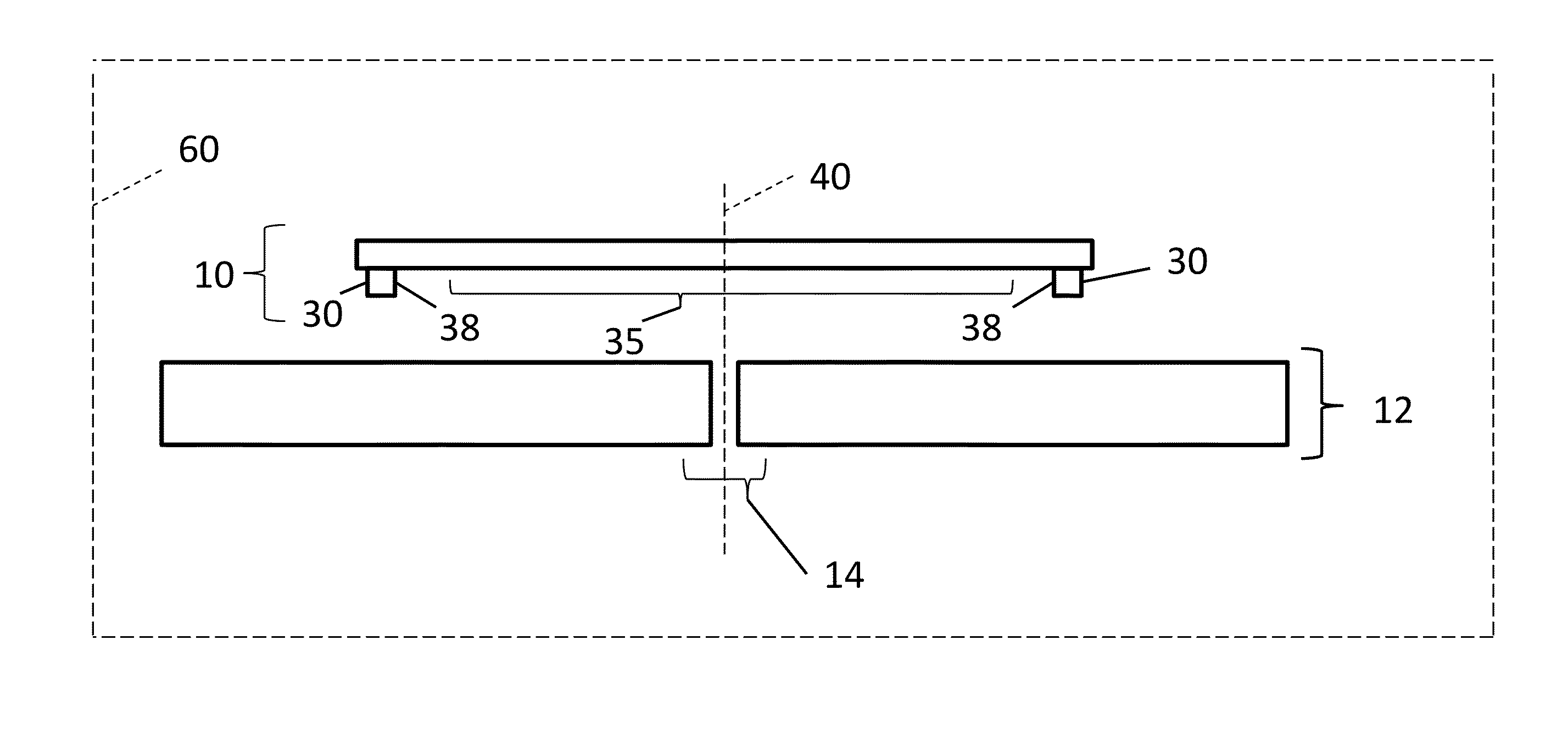
A substrate for fluidic levitation processing includes a moveable substrate and a levitation stabilizing structure located on the moveable substrate. The levitation stabilizing structure defines an enclosed interior impingement area of the moveable substrate that stabilizes lateral displacement of the moveable substrate during fluidic levitation processing.

Description

CROSS REFERENCE TO RELATED APPLICATIONS[0001]Reference is made to commonly-assigned, U.S. patent application Ser. No. ______ (Docket K001591), entitled “ATOMIC-LAYER DEPOSITION APPARATUS”, Ser. No. ______ (Docket K001859), entitled “ATOMIC-LAYER DEPOSITION APPARATUS USING COMPOUND GAS JET”, Ser. No. ______ (Docket K001860), entitled “ATOMIC-LAYER DEPOSITION METHOD USING COMPOUND GAS JET”, Ser. No. ______ (Docket K001862), entitled “COATING SUBSTRATE USING BERNOULLI ATOMIC-LAYER DEPOSITION”, all filed concurrently herewith.FIELD OF THE INVENTION[0002]The present invention relates to methods, equipment, and structures for depositing atomic layers on a substrate by employing Bernoulli effects.BACKGROUND OF THE INVENTION[0003]In general, the processing of substrates refers to the various steps performed or carried out to modify either the surface of a substrate material layer, the material layer of substrate itself, or both the surface of the material layer of the substrate and the mate...

Claims


Application Information

Patent Timeline
Patent Type & Authority Applications(United States)
IPC IPC(8): H01L21/68C23C16/458
CPCH01L21/68C23C16/4583C23C16/4585H01L21/67784H01L21/6838C23C16/4412C23C16/45544C23C16/45574C23C16/45576C23C16/458C23C16/4584
Inventor SIEBER, KURT D.NG, KAM CHUENCOK, RONALD STEVEN
Owner EASTMAN KODAK CO
Learn More