
Ceramic scintillator and its production method, and scintillator array and radiation detector

Active Publication Date: 2016-09-01
HITACHI METALS LTD
View PDF5 Cites 0 Cited by
  • Summary
  • Abstract
  • Description
  • Claims
  • Application Information

AI Technical Summary

Benefits of technology

The present invention provides a method for making a high-density ceramic scintillator that prevents a decrease in luminescence intensity.

Problems solved by technology

Because the rare earth oxysulfide powder obtained by the production method of JP 2000-313619 A contains large particles, high-density sintered bodies cannot be obtained by sintering under normal pressure.
To obtain high-density sintered bodies, hot pressing or hot-isostatic pressing should be conducted for sintering, resulting in high cost.
In the production method of JP 2004-525848 A, rare earth oxysulfide is wet-pulverized in a pulverizing organic liquid to adjust its particle sizes, but sulfur is dissociated from rare earth oxysulfide during pulverization, resulting in lattice defects due to the voids of sulfur introduced into rare earth oxysulfide.
The lattice defects remain even in a ceramic scintillator obtained by sintering rare earth oxysulfide, so that the ceramic scintillator has poor luminescence intensity.

Method used


Image

  • Ceramic scintillator and its production method, and scintillator array and radiation detector
  • Ceramic scintillator and its production method, and scintillator array and radiation detector
  • Ceramic scintillator and its production method, and scintillator array and radiation detector

Examples


example 1

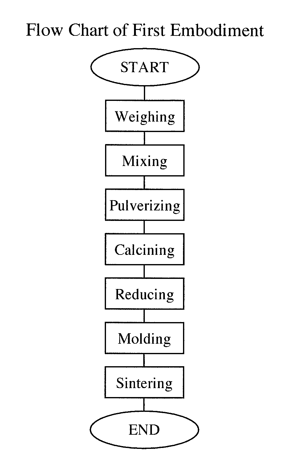
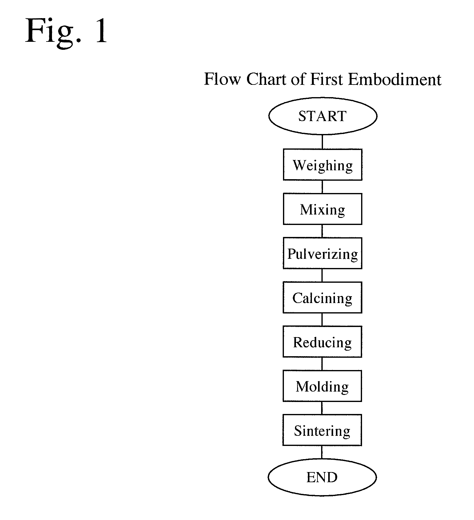
[0068]A ceramic scintillator was produced according to the first embodiment of pulverizing the product obtained by the mixing step.

[0069](1) Weighing Step

[0070]163.62 g of sulfuric acid having a concentration of 96% by mass was weighed and added to 1600 ml of pure water in a 3-liter beaker, to prepare dilute sulfuric acid.

[0071](2) Mixing Step

[0072]0.0113 g of cerium nitrate, 0.2561 g of praseodymium oxide and 290.00 g of gadolinium oxide were added in this order to dilute sulfuric acid in a 3-liter beaker. Diluted sulfuric acid was reacted with cerium nitrate, praseodymium oxide and gadolinium oxide to precipitate a product. The resultant suspension was heated to and kept at 90° C. for 150 minutes or more in a hot bath, while stirring by a stirrer.

[0073]The suspension was filtered by a Buchner funnel while stirring, to obtain a product. The product was dried at 120° C. for 12 hours, and then disintegrated by a mortar to sizes passing through a sieve having openings of 500 μm.

[0074]...

example 2

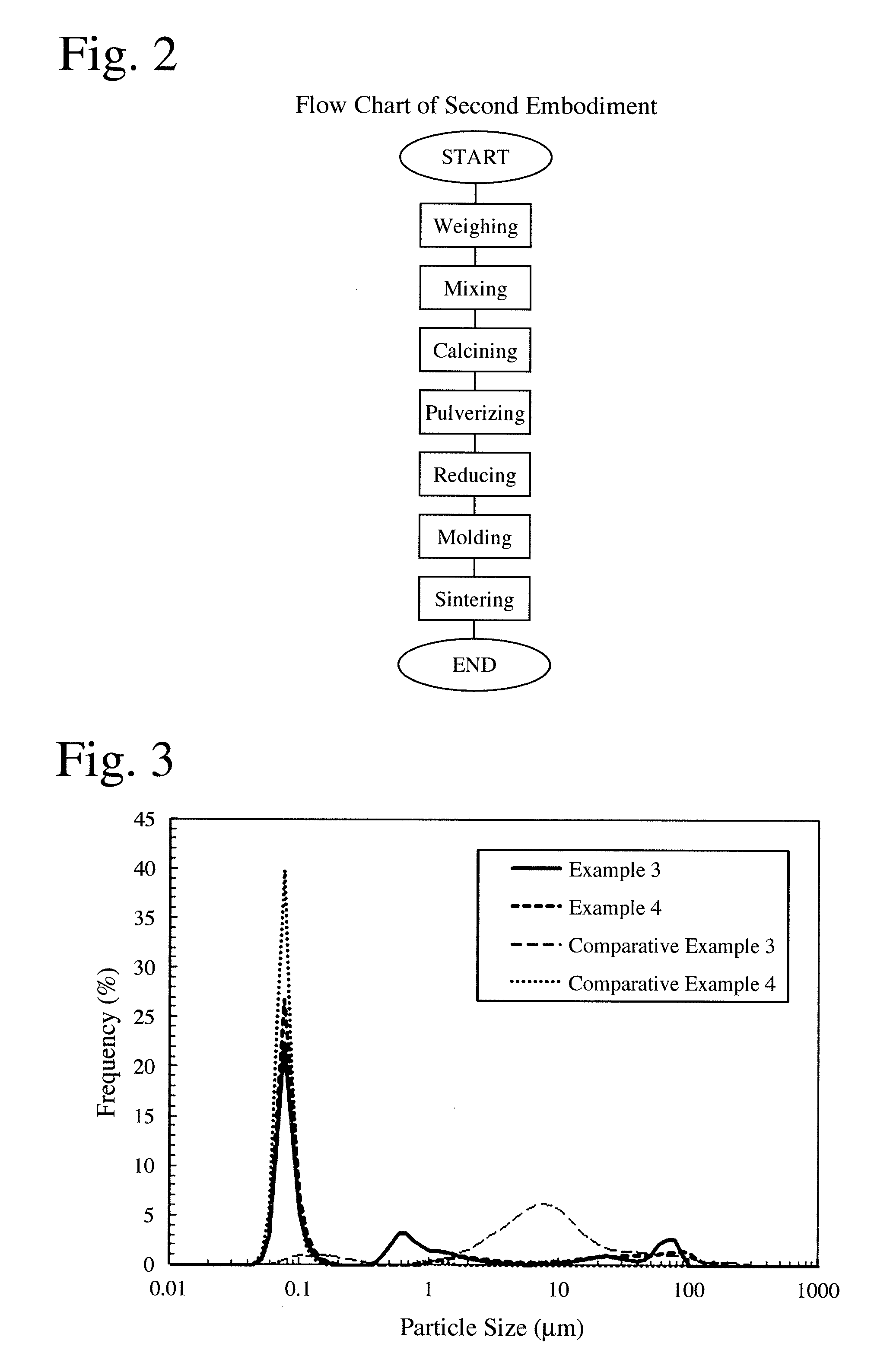
[0084]A ceramic scintillator was produced under the same conditions as in Example 1, except that the order of the pulverization step (3) and the calcining step (4) was changed according to the second embodiment, in which the calcined product was pulverized.

[0085]Namely, a reaction product obtained by the mixing step (2) was charged into an alumina crucible, and calcined at 900° C. for 1 hour in air at atmospheric pressure in a GOS calcining furnace. An H2O gas and an H2S gas generated by the reaction were disposed by a gas-treating apparatus.

[0086]100 g of the calcined product was charged into a ball mill together with 200 ml of ethanol, and wet-pulverized at 100 rpm for 15 hours. The pulverized slurry was dried at 100° C. for 4-6 hours. The dried product was disintegrated in a mortar to sizes passing through a sieve having openings of 500 μm, to obtain fine calcined product particles. The fine calcined product particles were subjected to the same reduction step (5), molding step (6...

example 3

[0094]Rare earth oxysulfide powder was produced by conducting the same weighing step (1), mixing step (2), pulverization step (3), calcining step (4) and reduction step (5) as in Example 1, except that 81.81 g of sulfuric acid having a concentration of 96% by mass was weighed in the weighing step, and that the pulverization time was 40 hours in the pulverization step. Using such rare earth oxysulfide powder, a ceramic scintillator was produced in the same manner as in Example 1.


PUM

PropertyMeasurementUnit
Temperatureaaaaaaaaaa
Pressureaaaaaaaaaa

Abstract

A method for producing a ceramic scintillator comprising the steps of mixing a rare earth compound with sulfuric acid and / or sulfate to cause their reaction to obtain a product; calcining the product to obtain calcined powder; reducing the calcined powder to obtain rare earth oxysulfide powder; molding the rare earth oxysulfide powder to obtain a green body; and sintering the green body; a pulverization step being conducted to adjust the particle sizes of the product and / or the calcined powder at least before the reduction step.

Description

FIELD OF THE INVENTION[0001]The present invention relates to a ceramic scintillator suitable for radiation detectors of X-ray CT apparatuses, etc., and its production method, and a scintillator array and a radiation detector using it.BACKGROUND OF THE INVENTION[0002]One of X-ray diagnosis apparatuses is a computed tomography (CT) apparatus. The CT apparatus comprises an X-ray tube for radiating X-ray fan beams, and a radiation detector comprising a large number of radiation detection elements. X-ray fan beams radiated from the X-ray tube pass through an object to be measured, and are detected by the radiation detector. The detected data are analyzed by a computer to display a cross section of the object. The measured data are analyzed by a computer to calculate X-ray absorbance at each position in each cross section of the object by a computer, thereby forming an image based on the X-ray absorbance.[0003]As radiation detectors for detecting radiations such as X-rays, etc., radiation...

Claims


Application Information

Patent Timeline
IPC IPC(8): C09K11/77G01T1/20
CPCG01T1/20C09K11/7771C01F17/294C01P2004/51C04B35/5156C04B35/547C04B35/6261C04B35/62645C04B35/6265C04B2235/3224C04B2235/3229C04B2235/44C04B2235/442C04B2235/443C04B2235/444C04B2235/447C04B2235/448C04B2235/449C04B2235/604C04B2235/662C04B2235/77G21K4/00
Inventor TERAZAWA, SHINSUKENITTA, HIDEO
Owner HITACHI METALS LTD
Learn More