
Set of polarizing plates and front-plate-integrated liquid crystal display panel

a liquid crystal display panel and front plate technology, applied in the field of sets of polarizing plates and front plate-integrated liquid crystal display panels, can solve the problems of liquid crystal display panel warping, liquid crystal display panel cannot be accommodated in the final product casing, and suppression of warping is not necessarily satisfactory, so as to achieve the effect of suppressing an amount of warping and being easy to accommoda

Active Publication Date: 2016-09-01
SUMITOMO CHEM CO LTD
View PDF2 Cites 8 Cited by
  • Summary
  • Abstract
  • Description
  • Claims
  • Application Information

AI Technical Summary

Benefits of technology

The present invention is about a special liquid crystal display panel that can withstand high temperatures and be easily placed into a case for a final product. The panel has a front plate that helps to prevent distortion and can be easily integrated into a final product.

Problems solved by technology

The above-mentioned recent tendency to reduce in thickness the front plate, the glass substrate used for a liquid crystal cell and the like, however, results in the warping of the liquid crystal display panel, which is attributed to the polarizing plates shrinkage in high temperature environments, and as a consequence, for example, a problem has arisen that the liquid crystal display panel cannot be accommodated in a casing for a final product.
However, a liquid crystal display panel's warping in a high temperature environment is attributed to a polarizing plate's shrinkage that depends upon a polarizer's thickness, as has been set forth above, and when the polarizer of the front-side polarizing plate is reduced in thickness, as described in PTD 1, a liquid crystal display panel having a front plate integrated using a pressure sensitive adhesive or an ultraviolet curing type resin for improved visibility, in particular, may have the warping, and suppression of the warping is thus not necessarily satisfactory.
When the method making protective layers different in thickness, as described in PTD 2, is applied to a liquid crystal display panel having a front-side polarizing plate with a front plate integrated therewith for improved visibility, however, a liquid crystal cell of the panel may have the warping resulting from the protective layer's thermal shrinkage and the problem may arise that the panel cannot be accommodated in a casing for a final product.

Method used


Image

  • Set of polarizing plates and front-plate-integrated liquid crystal display panel
  • Set of polarizing plates and front-plate-integrated liquid crystal display panel
  • Set of polarizing plates and front-plate-integrated liquid crystal display panel

Examples


example 1

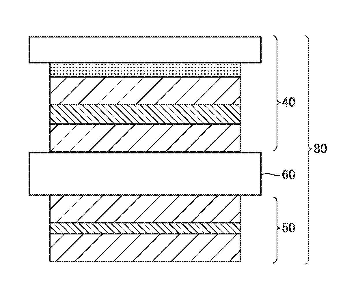
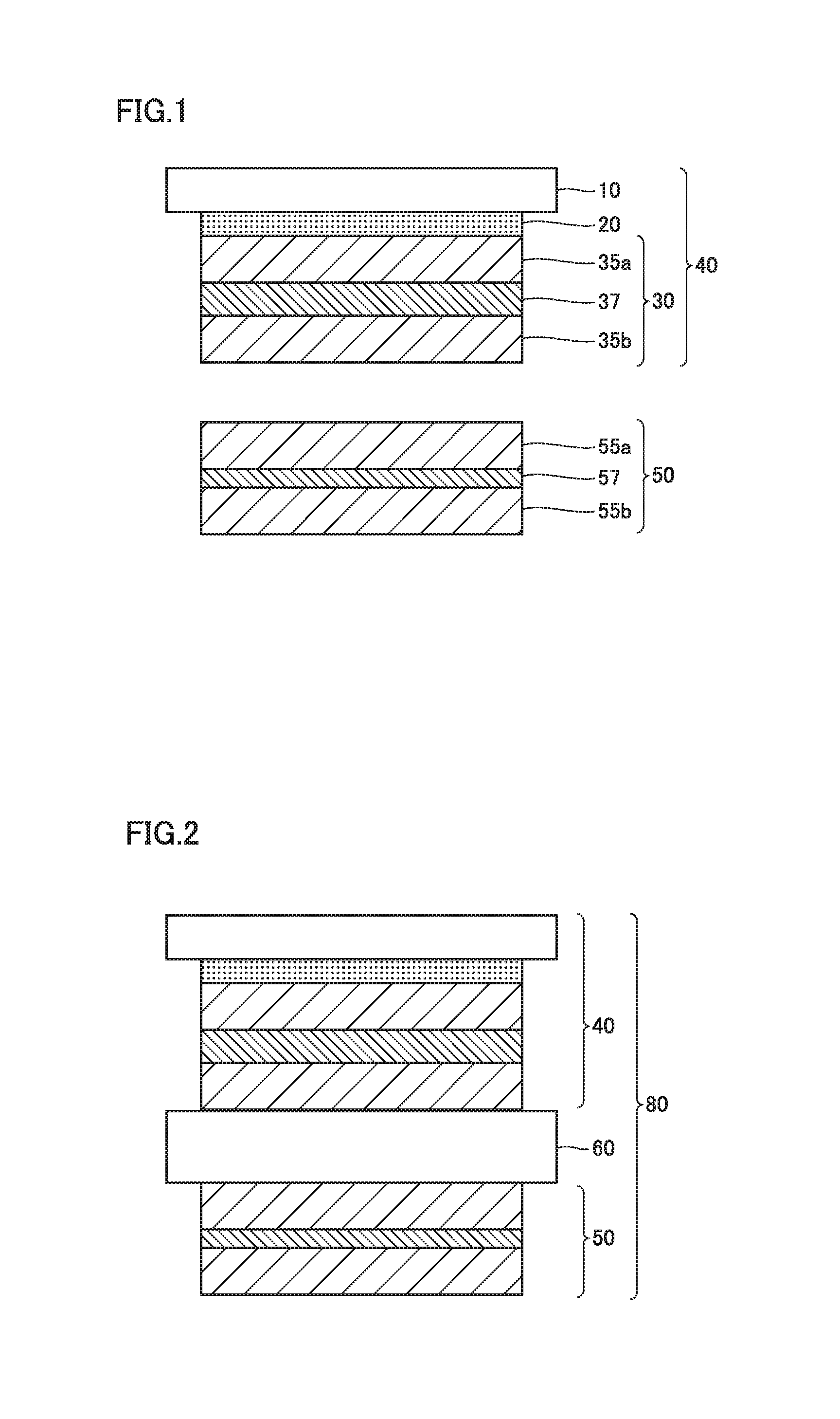
[0084]A front-plate-integrated liquid crystal display panel having a layer configuration shown in FIG. 2 was fabricated in the following procedure.

[0085](1) Fabrication of Front-Side Polarizing Plate 30

[0086]A 60 μm-thick polyvinyl alcohol film (with an average polymerization degree of approximately 2400 and a degree of saponification of 99.9 mol % or more) was uniaxially stretched by dry stretching with a stretching magnification of approximately five times and was immersed in pure water of 60° C. for one minute while maintaining the tension of the film and subsequently, immersed in an aqueous solution in which a weight ratio of iodine / potassium iodide / water was 0.05 / 5 / 100 at 28° C. for 60 seconds. Thereafter the film was immersed in an aqueous solution in which a weight ratio of potassium iodide / boric acid / water was 8.5 / 8.5 / 100 at 72° C. for 300 seconds. Subsequently, the film was washed with pure water of 26° C. for 20 seconds, and thereafter dried at 65° C. to obtain polarizer 3...

example 2

[0095]A front-plate-integrated liquid crystal display panel was fabricated in the following procedure. Note that while in the following description the reference characters indicated in FIG. 1 and FIG. 2 are used, unlike these figures, back-side polarizing plate 50 fabricated in the present example does not have protective layer 55a closer to liquid crystal cell 60 and a brightness enhancement film is laminated on an outer surface of protective layer 55b of back-side polarizing plate 50.

[0096](1) Fabrication of Front-Side Polarizing Plate 30

[0097]Front-side polarizing plate 30 identical to Example 1, item (1) was fabricated.

[0098](2) Fabrication of Back-Side Polarizing Plate 50

[0099]Acetoacetyl group modified polyvinyl alcohol powder having an average polymerization degree of 1100 and a degree of saponification of 99.5 mol % [trade name: “Gohsefimer Z-200” produced by The Nippon Synthetic Chemical Industry Co., Ltd.] was dissolved in hot water of 95° C. to prepare an aqueous solutio...


PUM

PropertyMeasurementUnit
Young's modulusaaaaaaaaaa
thicknessaaaaaaaaaa
in-plane phase retardationaaaaaaaaaa

Abstract

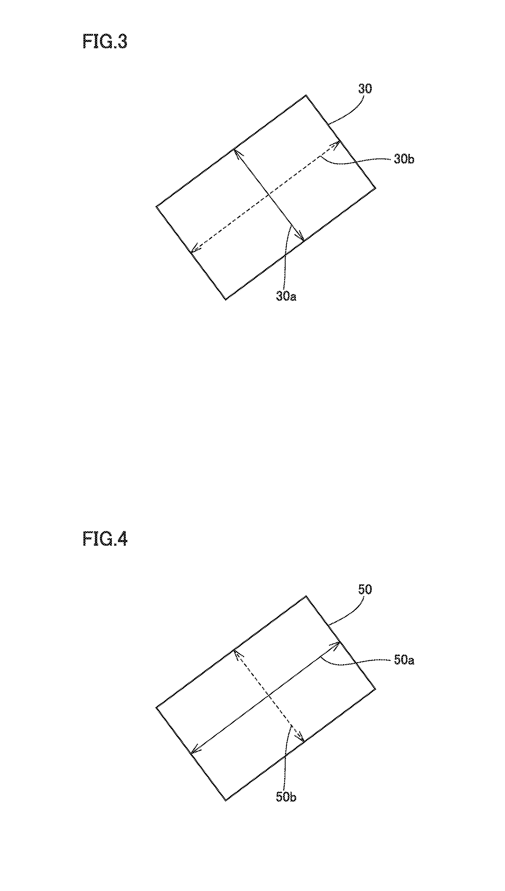
Provided is a set of polarizing plates comprising a front-plate-integrated polarizing plate to be disposed at a viewing side of a liquid crystal cell and a back-side polarizing plate to be disposed at a back side of the cell. The front-plate-integrated polarizing plate includes a front-side polarizing plate and a front plate having a Young's modulus of 2 GPa or more. The set of polarizing plates satisfies the formula: (Ra−Ft)<(Fa−Rt), where Fa and Ft represent ratios of dimensional change observed in the front-side polarizing plate in absorption and transmission axis directions, respectively, after the front-side polarizing plate is heated at 85° C. for 100 hours, and Ra and Rt represent ratios of dimensional change observed in the back-side polarizing plate in absorption and transmission axis directions, respectively, after the back-side polarizing plate is heated at 85° C. for 100 hours.

Description

TECHNICAL FIELD[0001]The present invention relates to a set of polarizing plates including a front-side polarizing plate having a front-plate integrated therewith and a back-side polarizing plate, and a front-plate-integrated liquid crystal display panel in which these polarizing plates are stuck on a liquid crystal cell.BACKGROUND ART[0002]Liquid crystal display devices have conventionally been used for desk calculators, electronic clocks, personal computers, etc. and in recent years there is an increasing demand therefor, and recently they are also applied to a wide range of applications such as mobile phones, tablet type terminals and the like. These liquid crystal display devices normally include as a main member a liquid crystal display panel including a liquid crystal cell with a pair of polarizing plates that are disposed on front and back sides of the liquid crystal cell.[0003]In the recent market, as mobile devices such as mobile phones and tablet type terminals having a sc...

Claims


Application Information

Patent Timeline
Patent Type & Authority Applications(United States)
IPC IPC(8): G02F1/1335G02B5/30
CPCG02F1/133528G02F2001/133567G02F2001/133562G02B5/3025G02F1/133562G02F1/133567
Inventor KAWAMURA, TAKAHITO
Owner SUMITOMO CHEM CO LTD
Learn More