
Surgical conduit leak testing

a surgical conduit and leakage detection technology, applied in the direction of measurement devices, structural/machine measurement, instruments, etc., can solve the problems of high leakage rate, layered conduits tend to be relatively thick-walled and not very flexible, and grafts still produce unacceptable leakage, etc., to achieve minimal assembly complexity, reduce the handling of two treated components, and pressurize relatively quickly

Active Publication Date: 2016-09-15
EDWARDS LIFESCIENCES CORP
View PDF7 Cites 11 Cited by
  • Summary
  • Abstract
  • Description
  • Claims
  • Application Information

AI Technical Summary

Benefits of technology

The patent describes leak testing systems and methods for commercial products that are non-destructive, efficient, and easy to use. The systems and methods can also be used for valved conduits that include a bioprosthetic valve and are sealed with a bioresorbable medium. The method involves leak testing the valved conduits using air and sealing them in dry packaging. The bioprosthetic heart valve can be treated to allow for extended storage without degradation of functionality. The sealed conduit includes a tubular matrix impregnated with a bioresorbable medium such as gelatin or collagen. The heart valve can be sewn to the end of the conduit or coupled thereto with a snap-fit connection to provide a hemostatic seal with minimal assembly complexity.

Problems solved by technology

Although such conduits are suitable in certain situations, and tend to seal relatively quickly to the body from tissue ingrowth, too much blood can initially seep through their walls after implantation, which may be detrimental.
Uncoated fabric such as polyethylene terephthalate (PET) has a high leakage rate, and thus the surgeon needs to pre-clot the graft with patient's blood before use.
Others have proposed using a non-bioresorbable sealant layer, such as silicone, for example, as described in U.S. Patent Publication No. 2008 / 0147171 to Ashton, et al., published Jun. 19, 2008, but such layered conduits tend to be relatively thick-walled and not very flexible, and so are not preferred.
Nevertheless, such grafts still produce unacceptable leaking.
Existing test methods are either destructive or require a drying period for the part.

Method used


Image

  • Surgical conduit leak testing
  • Surgical conduit leak testing
  • Surgical conduit leak testing

Examples


Embodiment Construction

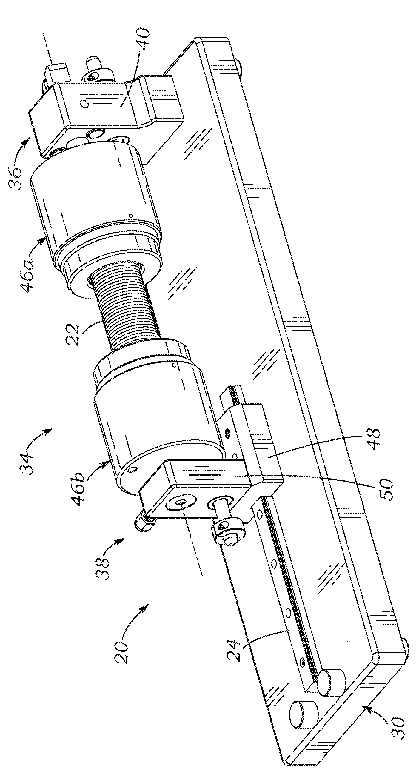
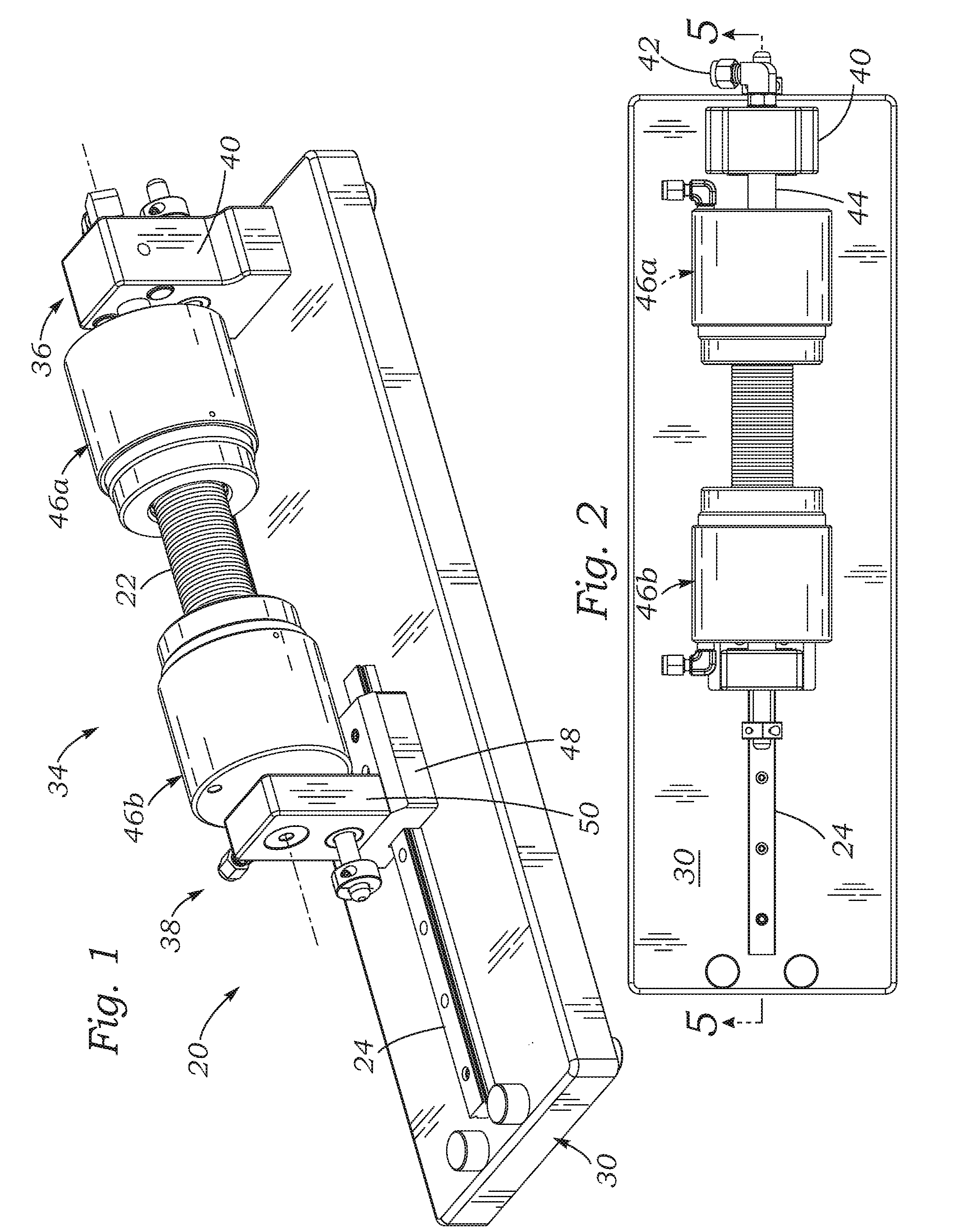
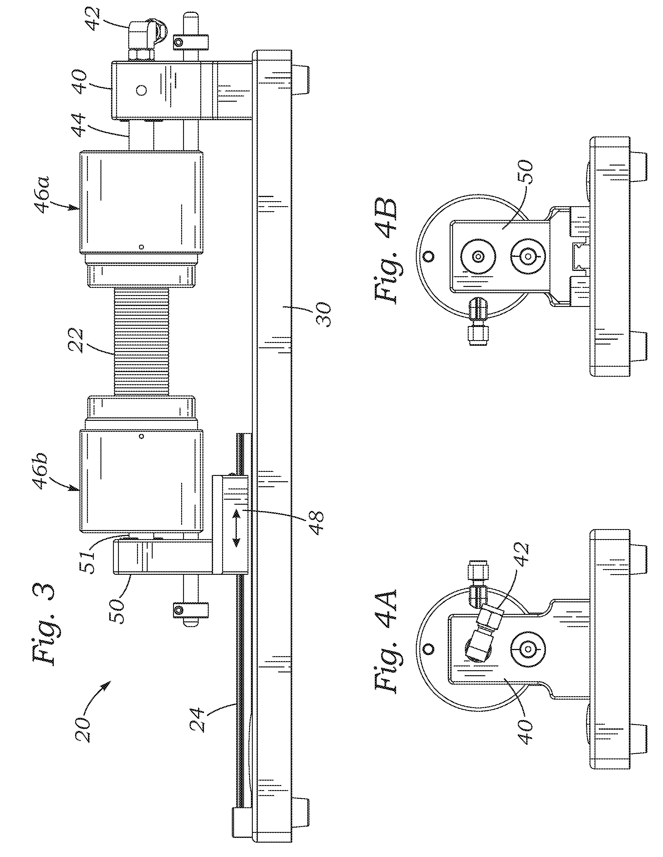
[0029]The present application discloses several systems for leak testing surgical conduits or grafts using a pressurized gas, such as air, as a testing fluid. In a preferred embodiment, pressurized air is the gas, although any gas that is non-destructive and non-reactive (inert) to the particular conduit being tested may be used, for example, oxygen, nitrogen, helium, argon, carbon dioxide, hydrogen, hydrocarbons, hydrofluorocarbons, fluorocarbons, fluorochlorocarbons, hydrofluorochlorocarbons, and combinations thereof. As used herein, the term “air” includes all suitable gas test fluids, except where context indicates otherwise. The use of a gas instead of a liquid testing fluid can preserve the surgical conduit, which may comprise porous tubular structures such as woven polyester (e.g., DACRON® PET, Invista, Wichita, Kans.) impregnated with bioresorbable materials such as gelatin, collagen, and / or albumin. In contrast, leak testing with liquid testing fluids can destroy the effica...


PUM


Abstract

Systems, devices, and methods for leak testing surgical conduit grafts or valved conduits such as aortic-valved conduits with a pressurized gas such as air. Air is non-destructive and especially useful for leak testing conduits that have coatings or sealants that may be functionally impacted when exposed to fluids such as water or saline. Open ends of the conduit are clamped and sealed, and a pressurized gas introduced into an inner lumen thereof. A change in mass flow rate is measured to quantify the leakage. One end of a tubular conduit may be clamped to a fixed manifold, and the opposite end to a manifold slidably mounted to accommodate any conduit elongation when pressurized. The clamping and sealing structure may be pneumatic and / or mechanical, and complementary contoured clamp members may be used to seal a scalloped external sealing ring of an aortic conduit.

Description

RELATED APPLICATIONS[0001]This application claims the benefit of U.S. Patent Application No. 62 / 131,134, filed Mar. 10, 2015, the entire disclosure which is incorporated by reference herein.FIELD OF THE INVENTION[0002]The present disclosure relates to systems and methods for leak testing surgical conduits, in particular, for leak testing valved conduits.BACKGROUND OF THE INVENTION[0003]Surgical valved conduits or grafts, including a prosthetic vascular conduit with an associated prosthetic valve to control flow of blood through the conduit, may be used for various purposes including, for example, the replacement of the aortic valve in conjunction with the ascending aorta. The aorta is the largest blood vessel in the human body, carrying blood from the left ventricle of the heart throughout the body. The ascending aorta is the first section of the aorta, which stems from the left ventricle and extends to the aortic arch. The aortic valve is located at the root of the ascending aorta ...

Claims


Application Information

Patent Timeline
IPC IPC(8): G01M3/28
CPCG01M3/2876G01M3/2807G01M3/2815G01M3/2846
Inventor VAN NEST, MARKKORNSWIET, ALYSSA E.LAU, JACKIE P.
Owner EDWARDS LIFESCIENCES CORP
Learn More