
Solar energy collection systems utilizing holographic optical elements useful for building integrated photovoltaics

a technology of solar energy and optical elements, applied in the field of solar energy collection systems, can solve the problems of not being commercially successful in the residential and building integrated photovoltaics (bipv) market, tracking systems have only shown marginal payback, and many attempts to improve the collection efficiency of photovoltaics have not been commercially viable, so as to achieve large angle of incidence ranges and improve efficiency

Inactive Publication Date: 2016-09-22
NITTO DENKO CORP
View PDF10 Cites 12 Cited by
  • Summary
  • Abstract
  • Description
  • Claims
  • Application Information

AI Technical Summary

Benefits of technology

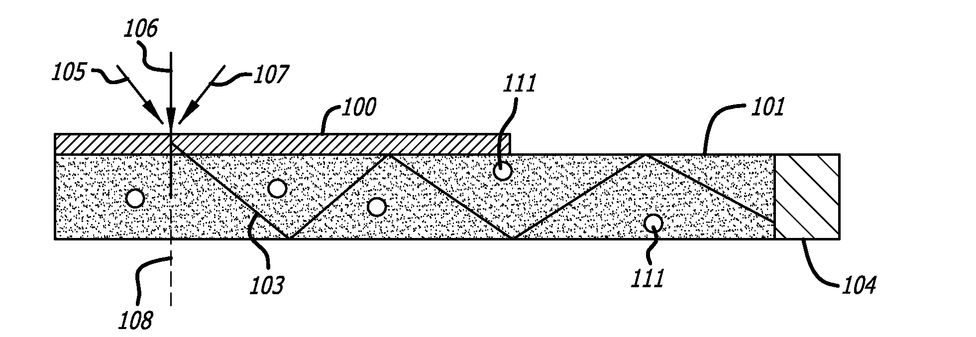
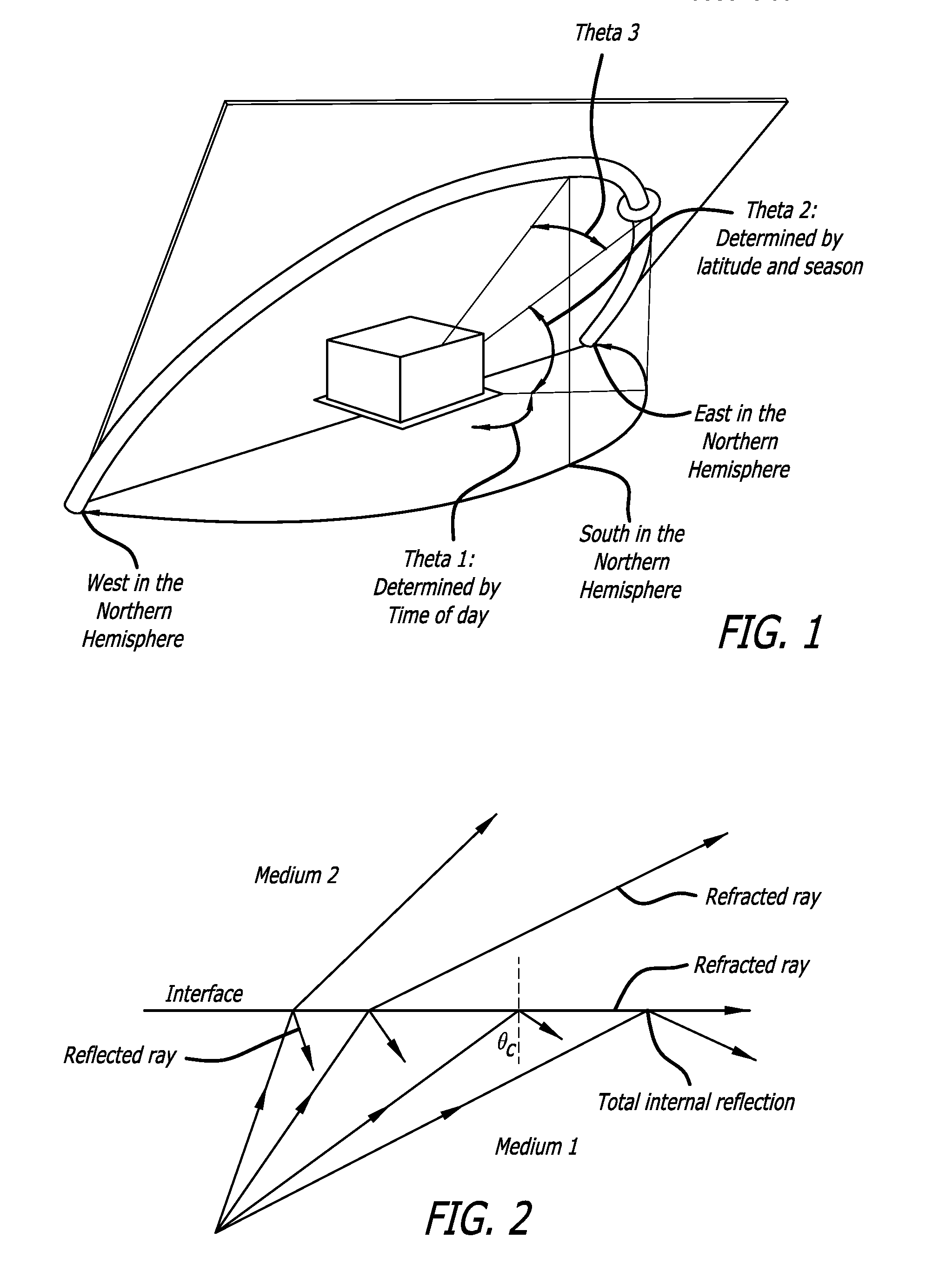
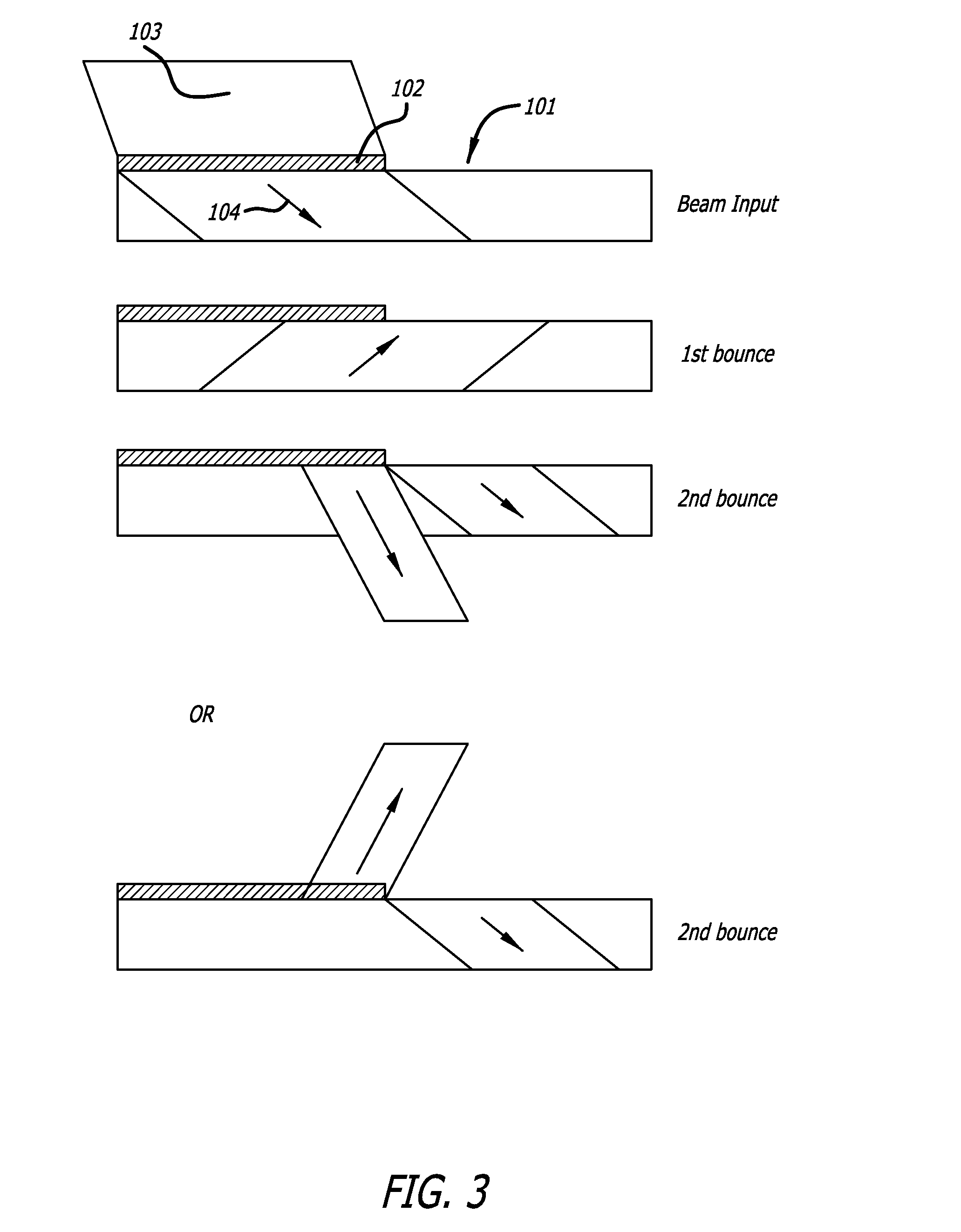
The present invention describes a transparent solar energy collection system that uses a holographic optical element, a transparent waveguide concentrator, and at least one solar energy conversion device. This system has improved efficiency and can collect solar energy from a large angle of incidence ranges without the need for mechanical or electrical tracking. The holographic optical element is optically attached to the transparent waveguide concentrator and diffracts light incident on the holographic optical element at different angles into the transparent waveguide concentrator. The system can also include additional layers to protect and refract photons, as well as a polymer layer to prevent harmful high energy photons from contacting the wavelength conversion layer and solar cell. Overall, this invention provides a more efficient and flexible way to collect solar energy.

Problems solved by technology

However, the photoelectric conversion efficiency of many of these devices still has room for improvement and development of techniques to improve this efficiency has been an ongoing challenge for many researchers.
Many attempts to improve the collection efficiency of photovoltaics have not been commercially viable due to their cost.
Therefore, for all but the largest commercial installations, tracking systems have demonstrated only marginal payback and have not been commercially successful in the residential and Building Integrated Photovoltaics (BIPV) markets where fixed systems predominate.

Method used


Image

  • Solar energy collection systems utilizing holographic optical elements useful for building integrated photovoltaics
  • Solar energy collection systems utilizing holographic optical elements useful for building integrated photovoltaics
  • Solar energy collection systems utilizing holographic optical elements useful for building integrated photovoltaics

Examples


examples

[0114]The embodiments will be explained with respect to preferred embodiments which are not intended to limit the present invention. Further, in the present disclosure where conditions and / or structures are not specified, the skilled artisan in the art can readily provide such conditions and / or structures, in light of the teachings herein, as a matter of routine experimentation.

example

[0115]The following example illustrates the procedures for fabrication of a HOE waveguide solar concentrator. This device allows collection of approximately 60% of the solar energy over the Sun's entire spectrum, which is shown in FIG. 24. This light is then guided into a glass substrate where it is channeled via TIR to a solar cell at its edge.

[0116]In our initial testing and fabrication, the recoding geometry was optimized for 45°. This corresponds to the Sun's elevation angle and for the in-coupling of light into the glass substrate. The wavelength range is centered at 900 nm, where solar cells are most efficient. DCG is characterized by having an extremely high modulation of refractive index (>0.1), and a transparency across the whole solar spectrum of >90%. Haziness can also be controlled to be <1%.

[0117]FIG. 24 shows spectral plots from two different HOE's and a combination of the two. These plots were measured using an UltraScan Pro Spectrophotometer in transmission mode. The...


PUM


Abstract

Described herein are transparent solar energy collection systems that comprise at least one holographic optical element, a transparent waveguide concentrator, and at least one solar energy conversion device.

Description

BACKGROUND[0001]1. Field[0002]The present disclosure generally relates to a solar energy collection system, and in particular, to novel systems utilizing holographic optical elements to maximize the collection of solar radiation as the sun changes position during the day without the need for mechanical or electrical tracking systems. In some embodiments, the system may also comprise luminescent wavelength conversion elements.[0003]2. Description of the Related Art[0004]The utilization of solar energy offers a promising alternative energy source to the traditional fossil fuels, and therefore, the development of devices that can convert solar energy into electricity, such as photovoltaic devices (also known as solar cells), has drawn significant attention in recent years. Different types of photovoltaic devices have been developed. However, the photoelectric conversion efficiency of many of these devices still has room for improvement and development of techniques to improve this effi...

Claims


Application Information

Patent Timeline
IPC IPC(8): H01L31/054H01L31/055
CPCH01L31/0543H01L31/055H01L31/0547G03H1/0248G03H1/202G03H1/24G03H2223/18G03H2260/10G03H1/0408Y02E10/52Y02A30/60
Inventor SIMAVORYAN, SERGEYWANG, PENGLIN, WEIPINGZHANG, HONGXIYAMAMOTO, MICHIHARUKITAHARA, ISAMALI, SHENGLACOMB, LLOYDBABLUMYAN, ARKADYRANKIN, RICHARD J.PEYGHAMBARIAN, NASSERORDYAN, ARMEN
Owner NITTO DENKO CORP
Learn More